hk backlight mod

Re: hk backlight mod
check the PDF file I posted above.. it has the pinout for both of them.. they're different..
My er9x/Ersky9x/eepskye Video Tutorials
https://www.youtube.com/playlist?list=PL5uJhoD7sAKidZmkhMpYpp_qcuIqJXhb9
Donate to Er9x/Ersky9x:
https://www.paypal.com/cgi-bin/webscr?cmd=_s-xclick&hosted_button_id=YHX43JR3J7XGW
https://www.youtube.com/playlist?list=PL5uJhoD7sAKidZmkhMpYpp_qcuIqJXhb9
Donate to Er9x/Ersky9x:
https://www.paypal.com/cgi-bin/webscr?cmd=_s-xclick&hosted_button_id=YHX43JR3J7XGW
Re: hk backlight mod
My guess is, turn the transistor around.. swap the 2 outside pins and it should work..
My er9x/Ersky9x/eepskye Video Tutorials
https://www.youtube.com/playlist?list=PL5uJhoD7sAKidZmkhMpYpp_qcuIqJXhb9
Donate to Er9x/Ersky9x:
https://www.paypal.com/cgi-bin/webscr?cmd=_s-xclick&hosted_button_id=YHX43JR3J7XGW
https://www.youtube.com/playlist?list=PL5uJhoD7sAKidZmkhMpYpp_qcuIqJXhb9
Donate to Er9x/Ersky9x:
https://www.paypal.com/cgi-bin/webscr?cmd=_s-xclick&hosted_button_id=YHX43JR3J7XGW
-
Daryoon

- Posts: 60
- Joined: Sun Jan 08, 2012 5:07 pm
- Country: -
- Location: http://www.hacksmods.com
- Contact:
Re: hk backlight mod
yeah, flip your transistor around. The two outer pins are reverse compared with the BS170.
-
pmackenzie
- Posts: 236
- Joined: Tue Dec 27, 2011 11:19 pm
- Country: -
- Location: Don Mills, Ontario
Re: hk backlight mod
To test a MOSFET short all the pins together with your fingers to discharge the gate.
The FET should be open circuit in the forward direction and a diode drop in the reverse direction. Gate will be isolated from both other pins.
Once you have the source figured out you can charge up the gate with the DVM probe and the FET should go low resistance in both directions.
Pat MacKenzie
The FET should be open circuit in the forward direction and a diode drop in the reverse direction. Gate will be isolated from both other pins.
Once you have the source figured out you can charge up the gate with the DVM probe and the FET should go low resistance in both directions.
Pat MacKenzie
-
Westy

- Posts: 248
- Joined: Tue Jan 31, 2012 8:44 pm
- Country: -
- Location: Te Awamutu, Waikato, New Zealand
Re: hk backlight mod
Thanks Chaps ....
You are as usual on the ball ... I can see they are reversed in the diagram..... trust me to get the drama eh? lol...... just wante a simple Bs170 to work..... but no ... its got to be different ... well the good news is we all learnt something today!!
Off to the Lab now to sort it .... back soon ... with hopefully good news!
Stay Tuned.
-
Westy
- Posts: 248
- Joined: Tue Jan 31, 2012 8:44 pm
- Country: -
- Location: Te Awamutu, Waikato, New Zealand
Re: hk backlight mod
Woo ... Hoo .....
That worked!!!
Cheers
Guys .....
hope someone one day finds this and it solves their problem with the 2N7000 Mosfet Mod.
thanks again folks....
Westy
That worked!!!
Cheers
Guys .....
hope someone one day finds this and it solves their problem with the 2N7000 Mosfet Mod.
thanks again folks....
Westy
Re: hk backlight mod
I found it and it did. Wired it all up and nothing, then I thought about this thread and double checked the data sheet, sure enough I had it back to front. Swopped it around and and it was like magic, light where there was no light
-
Westy
- Posts: 248
- Joined: Tue Jan 31, 2012 8:44 pm
- Country: -
- Location: Te Awamutu, Waikato, New Zealand
Re: hk backlight mod
Good on ya Billy boy!
Re: hk backlight mod
Hi All,
This mod to add a HK backlight module is quite confusing re the supplied module from HobbyKing.
Depends on where you look as to what has to be done to this PCB for correct operation
of the 9x after fitting it.
Some refer to having to cut the track leading to pin 5 and then connecting the resistor to
pin 3. I have all three colours BL's and just received these and they all have the resistor feeding
the BL module from pin 5.
The wiki pics for switching the BL on and off show a board with the resistor connected to
pin 5.
So if pin 5 connection is correct then wiki is fine, if not it will need changing.
Could someone who is accurately knowledgeable please clarify.
I just want to make sure those were confused thru reading so much, can refer to the wiki
with some confidence.
Thanks for a great site and everything i ve gained(still learning) from this site has been very much
appreciated.
Regards
Les
-
Westy
- Posts: 248
- Joined: Tue Jan 31, 2012 8:44 pm
- Country: -
- Location: Te Awamutu, Waikato, New Zealand
Re: hk backlight mod
Are you talking about on the Actual HK little PCB?
Not sure what you are talking about with pin 5 and pin 3??
for the mod there are 2 types of Mossfet you use BS170 and 2N7000 series (both a wired in differently)
You connect you BL panel to here like this
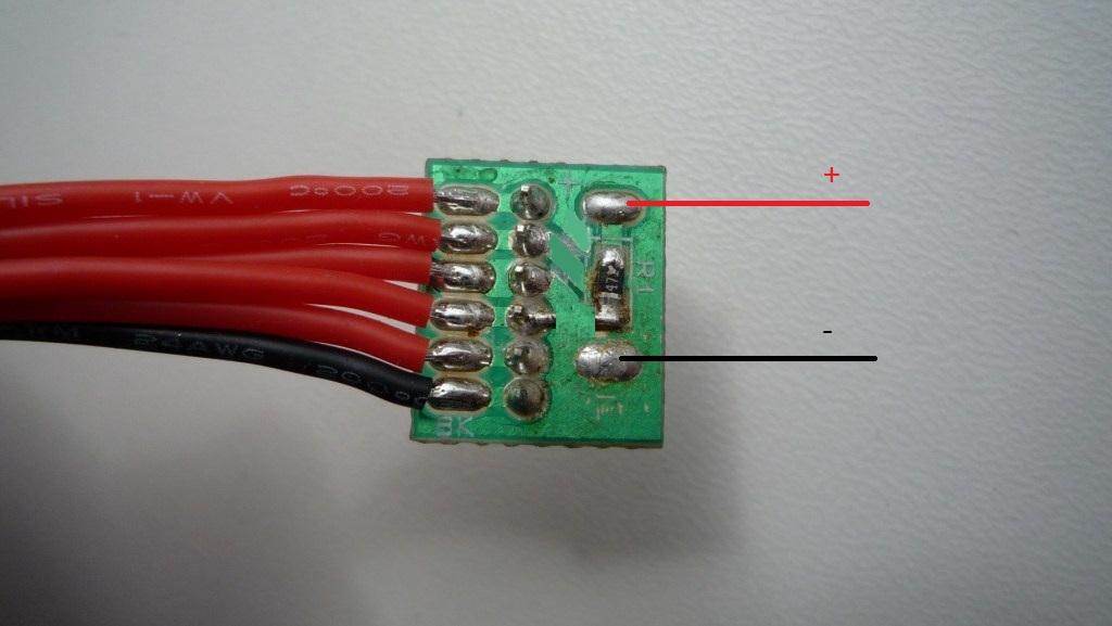
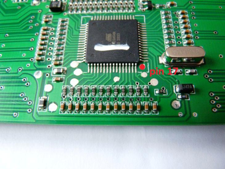
and a wire connects to this pin on the board:
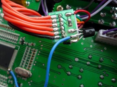
and to the mosfet like this:
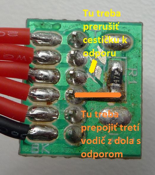
Then the board link need to be cut here ( YELLOW MARK) ..... and a piece of the old mosfet leg soldered between the resistor and the pin adjacent like so (ORANGE MARK)
Not sure what you are talking about with pin 5 and pin 3??
for the mod there are 2 types of Mossfet you use BS170 and 2N7000 series (both a wired in differently)
You connect you BL panel to here like this
and a wire connects to this pin on the board:
and to the mosfet like this:
Then the board link need to be cut here ( YELLOW MARK) ..... and a piece of the old mosfet leg soldered between the resistor and the pin adjacent like so (ORANGE MARK)
Re: hk backlight mod
Hi Westy,
Thanks for the clarification. The pin numbering i was referring to is for the HK backlight wee pcb. Black wire is pin 3
and the 470 ohm resister is connected to pin 5 as original. The wiki shows this mosfet mod but shows no cutting of the pcb at
pin 5. You have to go further thru the thread to find it. I think a wee note on the wiki underneath the pic of the pcb
asking people to check if the resistor goes to pin3 or 5 and show that it should be cut if connected to pin5. Thsi gets over the
problem if HK ever fix the error.
One this makes sense from one Kiwi to another.
Reagards
Les
-
Westy
- Posts: 248
- Joined: Tue Jan 31, 2012 8:44 pm
- Country: -
- Location: Te Awamutu, Waikato, New Zealand
Re: hk backlight mod
hey there,
Can you post the wiki page so I can have a look at it?
If you also not that the BS170 shown here.... it is connected with the flat to the board
.... and the 2N7000 is flat side up to you.....
Can you post the wiki page so I can have a look at it?
If you also not that the BS170 shown here.... it is connected with the flat to the board
.... and the 2N7000 is flat side up to you.....
-
Westy
- Posts: 248
- Joined: Tue Jan 31, 2012 8:44 pm
- Country: -
- Location: Te Awamutu, Waikato, New Zealand
Re: hk backlight mod
How is this?
I have added a bit in there to make it clearer..... hope this will help
http://openrcforums.com/wiki/index.php/ ... _Backlight
I have added a bit in there to make it clearer..... hope this will help
http://openrcforums.com/wiki/index.php/ ... _Backlight
Re: hk backlight mod
Thanks Westy,
Perfect
Les
Perfect
Les

hk backlight mod
I want to add the transistor and switch the HK led with the firmware. However, I don't want to keep the inline plug for the backlight. I would prefer to eliminate all that extra bulk. The mod as shown here http://openrcforums.com/wiki/index.php/ ... ircuit.jpg has a 470 resistor in the left wire. Is that in addition to the resistor in the stock backlight connector?
I am also trying to figure out what transistor I can use. I don't have any I can salvage so I have to buy one. Will this alternate work? http://www.radioshack.com/product/index ... ransistors
I am also trying to figure out what transistor I can use. I don't have any I can salvage so I have to buy one. Will this alternate work? http://www.radioshack.com/product/index ... ransistors
Re: hk backlight mod
Cant see a problem with that, its only a switch and the specs on the one you have linked are better than the one suggested. I used the same tranny when I did my Haptic mod after naffing the original. As for the resisitor I would think that, that would be the only resistor you would need as the resistor on the board is 470 ohm
http://alltransistors.com/ type in the transistor number you have, or look through the numbers on the left and then search, it will give the specs for that tranny and further down the page you will see some equivalents.
http://alltransistors.com/ type in the transistor number you have, or look through the numbers on the left and then search, it will give the specs for that tranny and further down the page you will see some equivalents.
-
cre8tiveleo

- Posts: 1434
- Joined: Tue Dec 27, 2011 6:13 pm
- Country: -
- Location: Ontario,(GTA North)
- Contact:
hk backlight mod
I don't use the hk harness at all. 1k ohm resistor works nicely, depending on the resistor value, will deterime bklght brightness.
Crucial, I have spare transistors somewhere, pm me your addy, i'll mail one to you.
Crucial, I have spare transistors somewhere, pm me your addy, i'll mail one to you.
Re: hk backlight mod
I appreciate the offer to mail one but I am planning on installing 2 backlights this weekend so I need them sooner than that.
Re: hk backlight mod
I will have to play around with the resistor. I take it it the value and brightness depends on where you are getting your power and the voltage of your battery. Creativeleo where are you tapping your power from?

Re: hk backlight mod
Yes, a pic of how you tap the transistor would be great.
Re: hk backlight mod

Does anyone know the purpose of the jumper wire and cut track? When I measure the voltage at either of those points it is the same. Both are battery voltage and are switched with the main power switch.
-
pmackenzie
- Posts: 236
- Joined: Tue Dec 27, 2011 11:19 pm
- Country: -
- Location: Don Mills, Ontario
Re: hk backlight mod
I think it has something to do with power for the RF module.
The way the stock HK board is the RF module gets powered up when you plug in the trainer cord.
The way the stock HK board is the RF module gets powered up when you plug in the trainer cord.
-
Westy
- Posts: 248
- Joined: Tue Jan 31, 2012 8:44 pm
- Country: -
- Location: Te Awamutu, Waikato, New Zealand
Re: hk backlight mod
Hmmmm..... Interesting question, I have my doubts it make any difference at all..... although it would be an interesting exercise to trace Positive wire 3rd from left and 4th from the left to see where they source and go to.....

Re: hk backlight mod
As stock (3rd pin), it follows module power, which means the backlight will not be powered if the radio has the power switch off, but is turned on by connecting a jack in the trainer port.
On pin 5 it will be on everytime the TX is on whatever the means.
I.e. if you use a simulator in front of your PC in a dark room, you'll want to do the mod
On pin 5 it will be on everytime the TX is on whatever the means.
I.e. if you use a simulator in front of your PC in a dark room, you'll want to do the mod
hk backlight mod
That makes sense. I seem to remember reading something about that now. I removed the HK board and have tried hooking it up a few different ways with a transistor and 470ohm resistor. The best way so far has been as described here. Hooking the resistor in line with the positive side and running the ground though collector and emitter. Now I just have to figure out a nice clean and compact way of wiring it up.
hk backlight mod
This is the first HK backlight I've used. I noticed that there is no flickering of the stick values when the light is on. All of my smartie parts el panels cause the flickering.
Re: hk backlight mod
- Alternate solder point
hey, instead of soldering the little wire to the bottom of the resistor, can I instead solder the end to the point in the attached pic? (just where I'm supposed to cut) It seems that it would be easier for me to solder there, and avoid damaging the resistor. I have a 30 watt soldering iron, and if I can solder further away from it, the more likely I won't damage it.....
-
Westy
- Posts: 248
- Joined: Tue Jan 31, 2012 8:44 pm
- Country: -
- Location: Te Awamutu, Waikato, New Zealand
Re: hk backlight mod
that should be fine ..... as long as teh trace cut is large enough.
Re: hk backlight mod
hi guys
what you thing about idea reversing polarization foil for little bit different look, black background and red symbols...is it possible?
http://www.icehw.net/article.php?id=65
what you thing about idea reversing polarization foil for little bit different look, black background and red symbols...is it possible?
http://www.icehw.net/article.php?id=65