The name pretty much covers it; if you want to change the color of your 9XR/9XR Pro's LCD backlight, then you're in the right place.
You will need:
5) 3020 size BRIGHT WHITE LEDs, 3500mCD or higher
1) 1206 size 22Ω SMD Resistor (Or 2 0805 size resistors totaling 17-22Ω in series or parallel)
A decent, temperature-controlled soldering station with a 0.1mm fine tip
Very fine solder (I prefer Radio Shack # 64-035 0.015" Silver-Bearing Solder for this type of delicate work)
Fine-braid Solder-Wick or equivalent desoldering braid
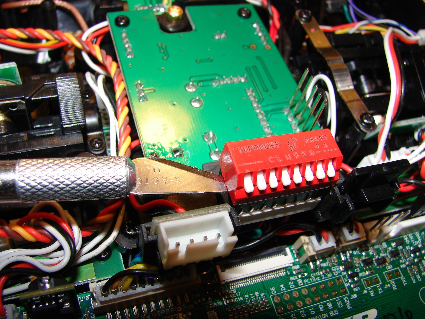
An X-Acto Knife with a halfway decent # 11 blade
Some patience and a little technical ability.
First, we need to get some new LEDs. The ones I used came from this vendor:
http://www.ebay.com/itm/350349379262
No ePacket shipping, so they arrived in about 12-13 days.
Your other option is to go to eBay, type "3020 White LED" in the Search box and wade through the 7-10 pages of hits, looking for the one or five listings that AREN'T some sort of idiotic mood lighting for that kid with the saggy pants to put in his Hoopty.
If you want another color besides the ones in that listing, I'm afraid you're going to have to brave that tidal wave anyways. Sorry.

Don't bother with the "Purple" ones; most of their emission is in the UV range. Unless you want to see that mustard stain on your shirt glow in the dark, they're useless as backlights.
Remember that different color LEDs have different Forward Voltage; this means you'll need to calculate different values for R56. You are calculating for a MAX forward current of 55-70mA total with a source voltage of 5V; that drives these LEDs at 11-14mA each. This leaves a little wiggle room for variations in the current draw of individual LEDs.
You can use the LED calculator here to help you:
http://ledcalc.com/
Remember that the 9XR uses a source Voltage of 12.6V, while the 9XR Pro uses 5V. Treat the entire array as a single LED needing 55-80mA of current to drive it.
Plug in the Forward Voltage of the LEDs you are buying. Remember that the calculator will choose the next higher resistance standard value resistor; if that doesn't produce enough current, move to the next lower value and try again.
As a comparison, I'm driving Red LEDs in a similar array with a 33Ω ballast resistor at 5V, as well as Aqua Green and Blue ones with 22Ω resistors. These values produce very conservative current draws in the ranges shown above. Orange, Amber, Yellow and Pure Green LEDs will typically have forward voltages similar to the Red LEDs used above, so will probably need closer to the 33Ω ballast.
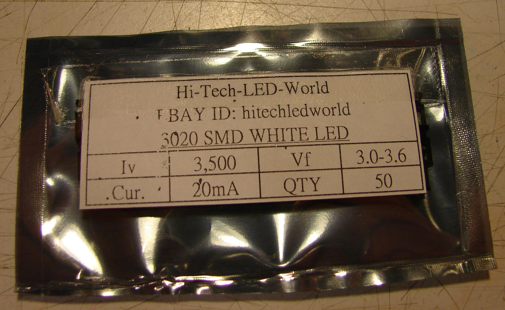
$5.00 got me 50 pieces with shipping. These LEDs are pretty awesome; you'll find a use for the rest of 'em.
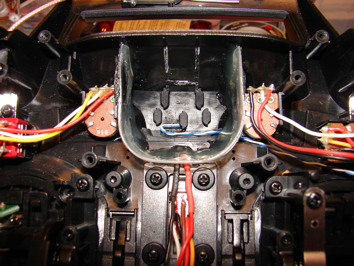
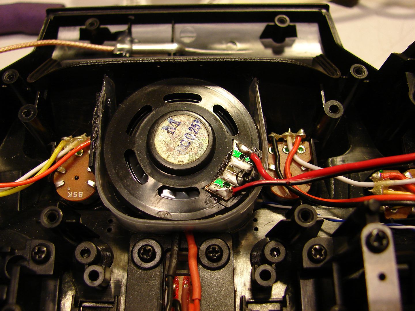
For the sake of progress, we'll assume you're capable of removing the backlight without destroying your radio. If you aren't, ummm... sorry. This isn't a job for the timid or the completely non-tech-inclined.
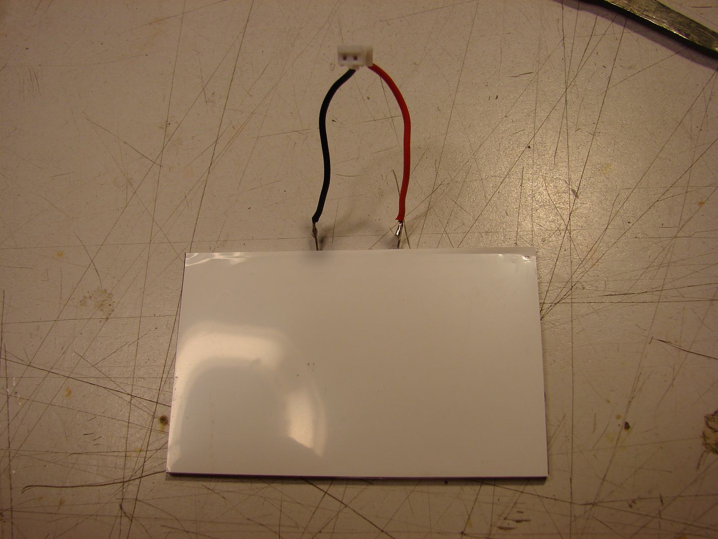
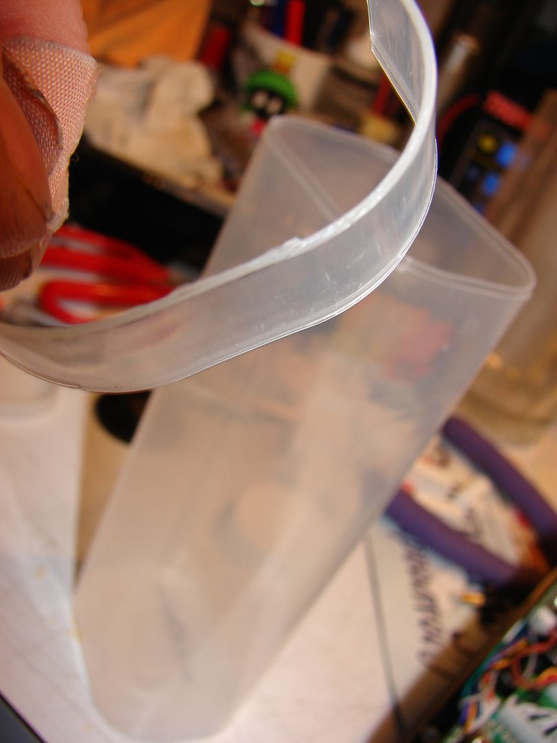
The backlight has a translucent side, and a nearly-opaque white side. The white side is the back.
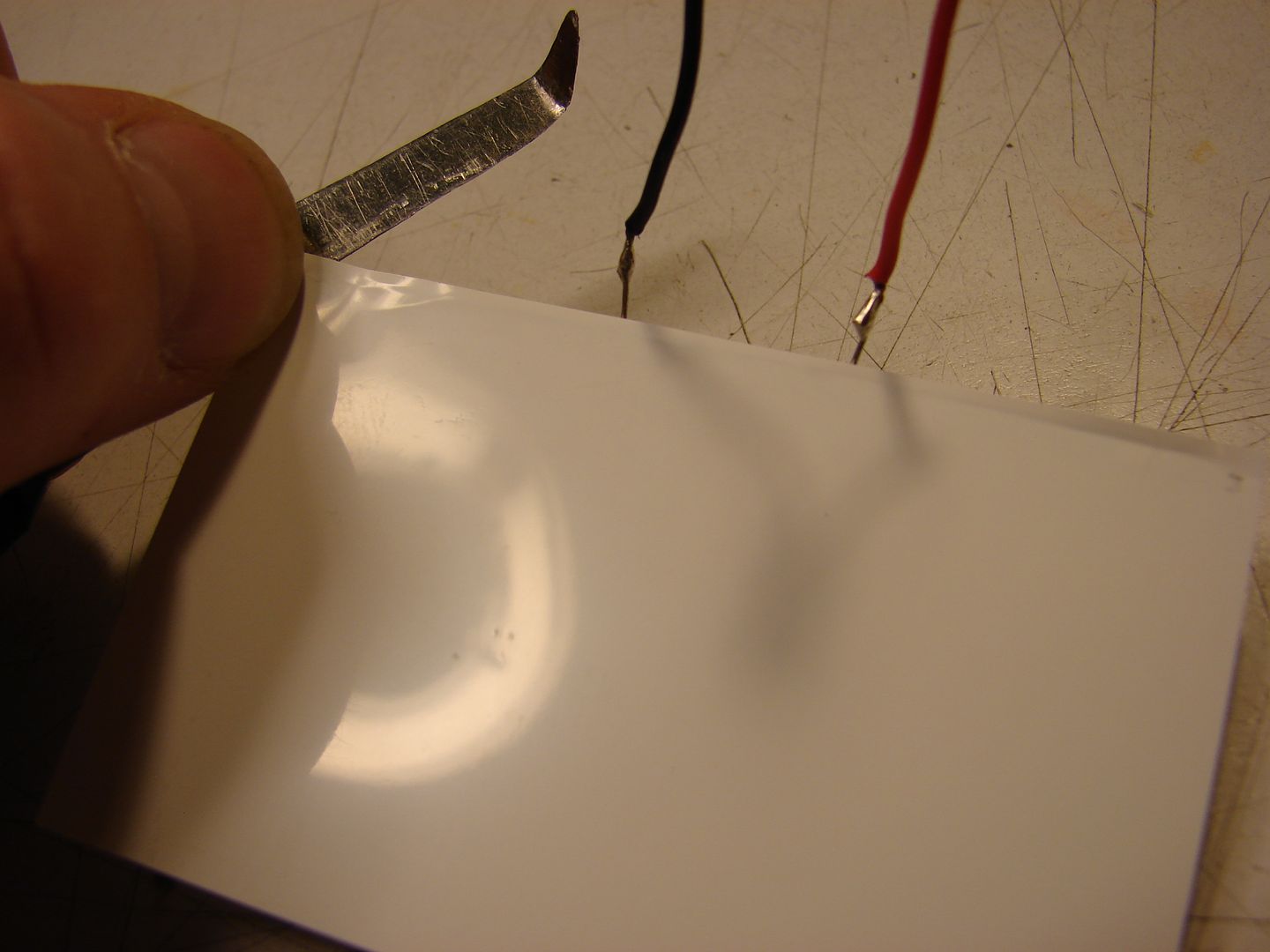
The back is held on with two thin strips of double-faced tape. Using the edge of a paring knife, start lifting the white plastic sheet at one of the corners on the edge with the LED strip. Be VERY CAREFUL handling the backlight so as not to scratch the front side; it is possible to scar it badly enough that you can see it through the LCD.
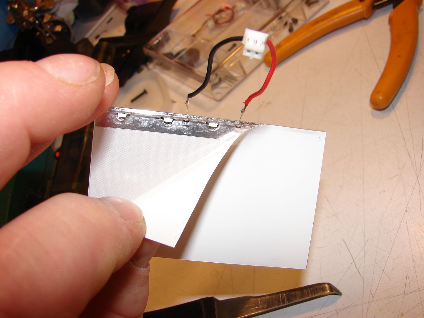
Continue peeling back the white sheet ...
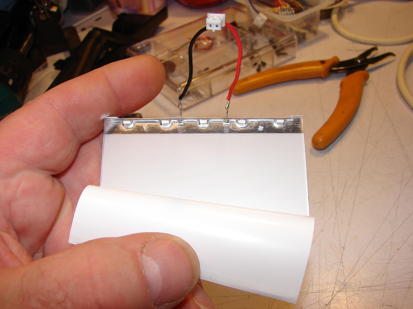
...and now the LED strip can be seen.
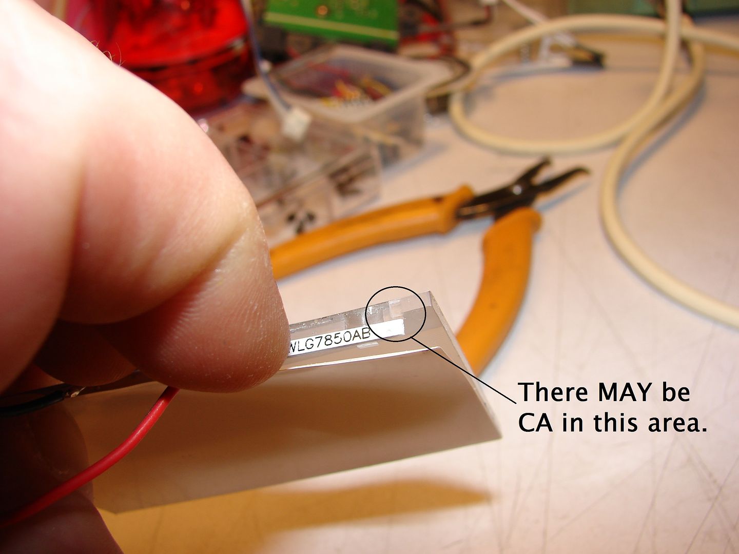
On my 9XR, the LED strip just slid into this slot at each end of the backlight lens. On my 9XR Pro, they had CA (Superglue) to hold it in place. By repeatedly gently pulling the LED strip away from, then pressing it back down on the lens at about 3/4" (20mm) from each end, you can break the CA loose, then slide the LED strip free.
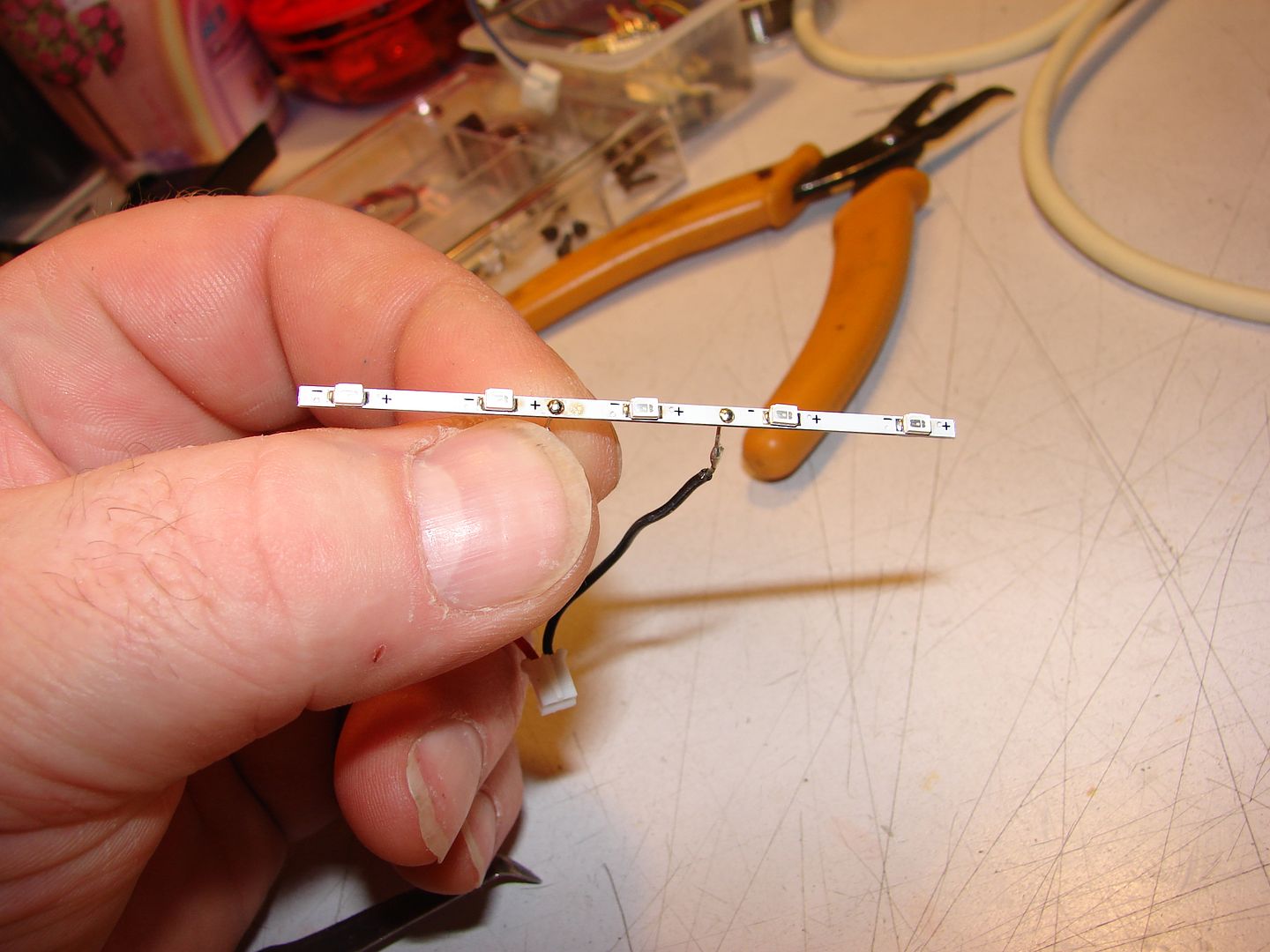
And here's the LED strip out of the lens. Note that polarity is marked at each LED. Maybe they were expecting us...
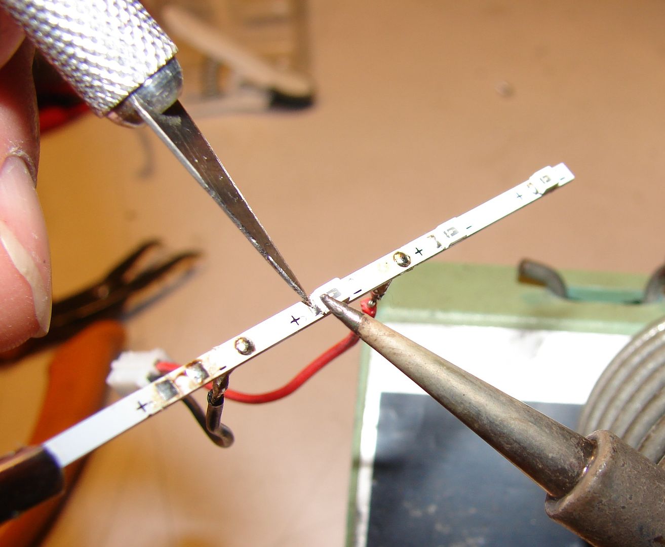
By applying heat with the tip of a soldering iron, you can slip the tip onf an X-Acto knife under the solder joint; lift up just enough to separate the solder from the LED. Repeat on the other side and the LED will fall off.

Touch up the pads with a little desoldering braid to get them ready.
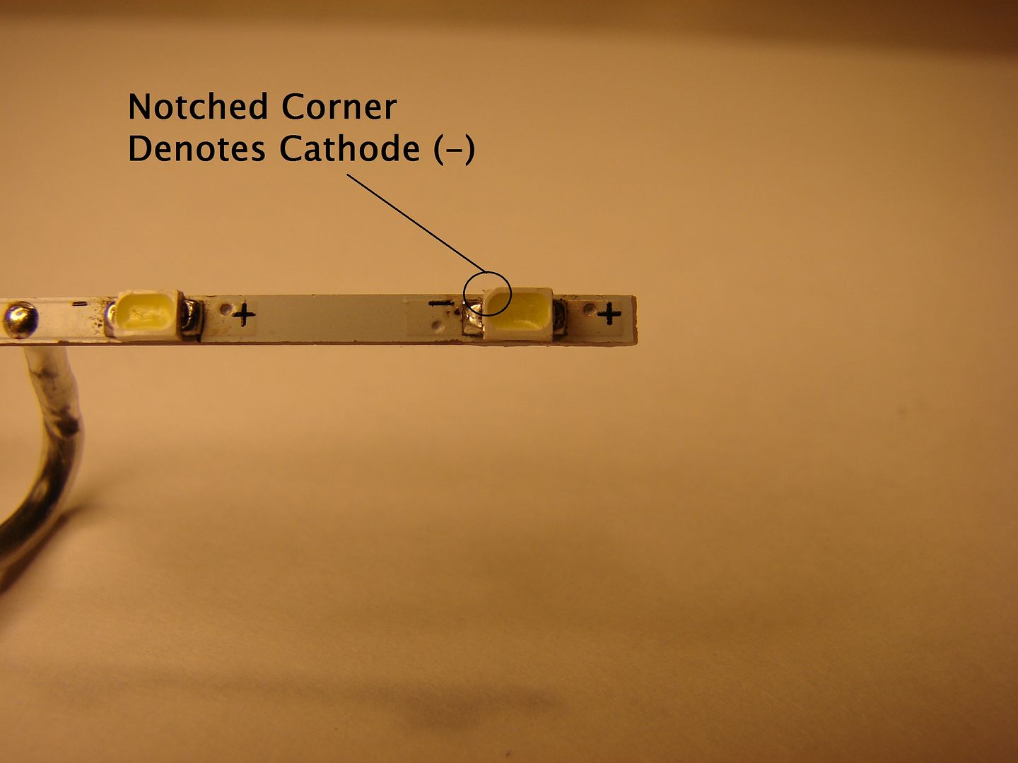
Now it's pretty simple; just hold the LEDs in place and tack the solder tabs to the pads on the LED strip. Note that the notch denotes Cathode (-) tab on LED.
Once you have them all tacked down, go back over with a cleaned iron tip and fresh solder, making sure the LEDs are all straight.
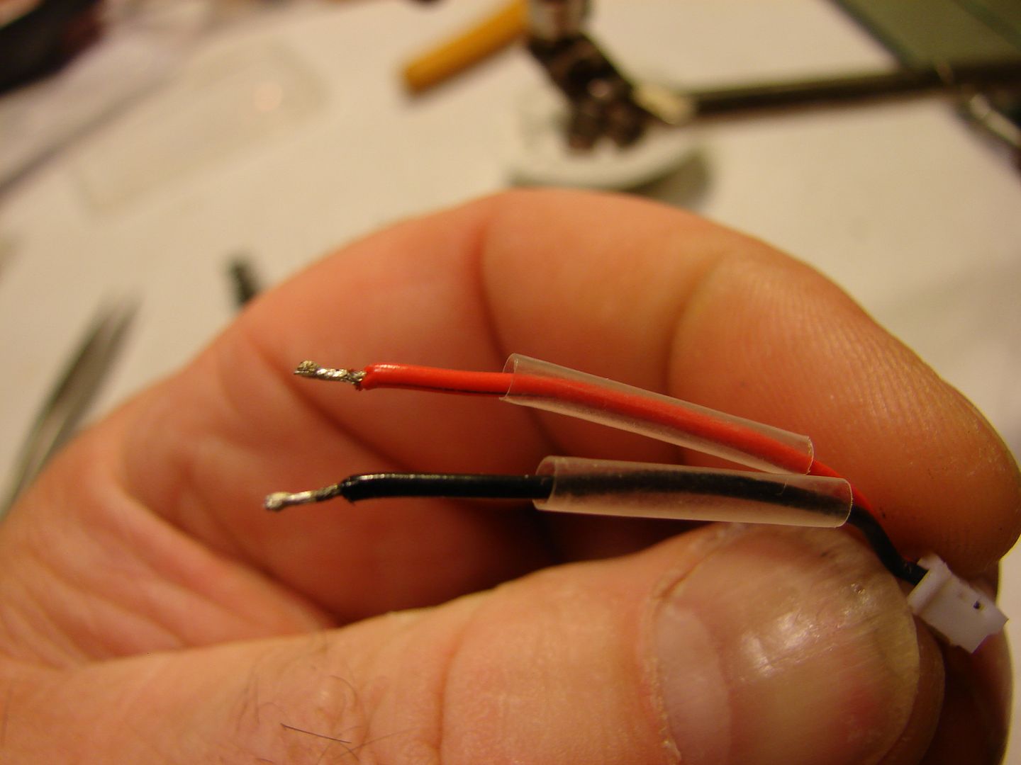
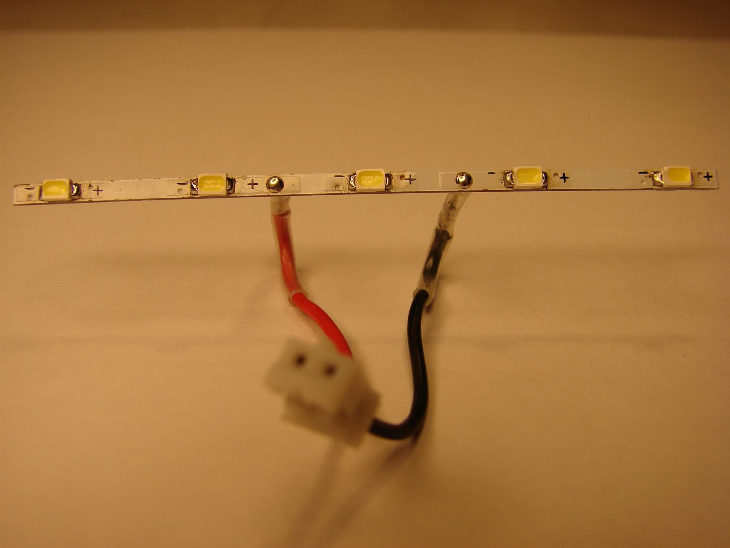
While you have everything apart, I suggest unsoldering the leads from the LED strip and adding a little heat shrink tubing...
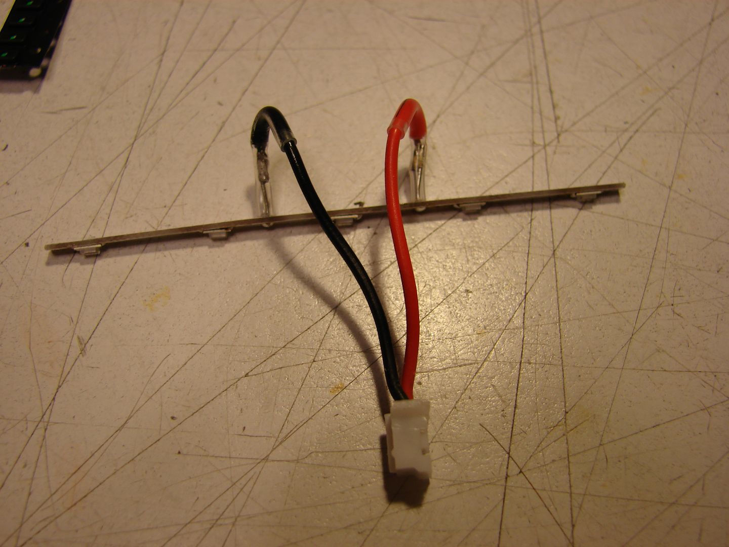
... you'll need to put a little "pre-curve" into the leads & heat-shrink while it's still hot so everything still plugs in as it should.
If you're working on a 9XR the OEM ballast resistor is pretty close to nominal value already, as the LEDs are driven from full battery voltage. It drives these LEDs at 55mA total, or approx 11mA each. You can move onto reassembling your backlight and testing.
If you have a 9XR Pro, there's a little extra work you'll need to do...
These LEDs have a slightly higher Forward Voltage than the original Blue LEDs; if you haven't already done my "9XR Pro Dim LED Backlight Mod", you'll need to now.
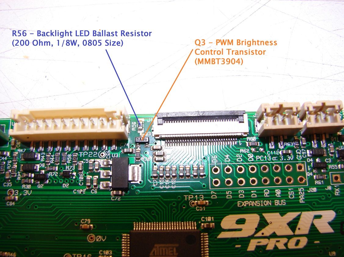
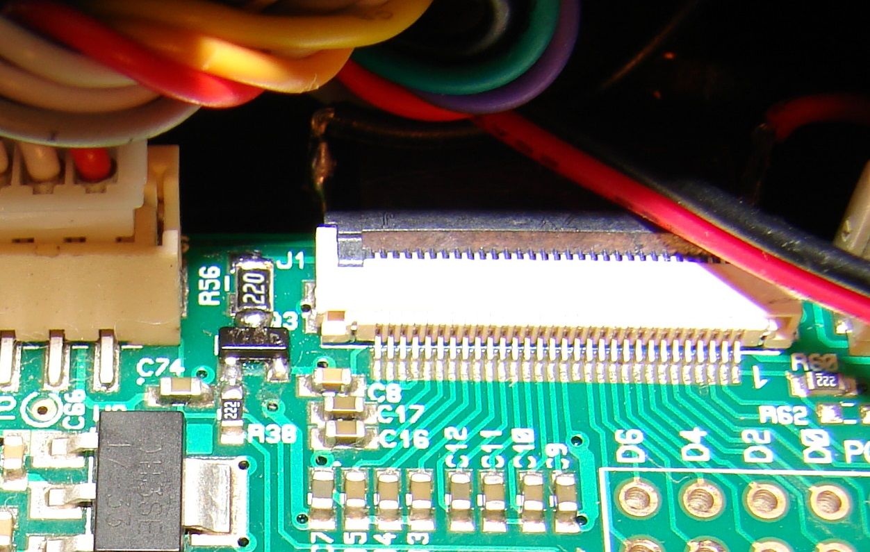
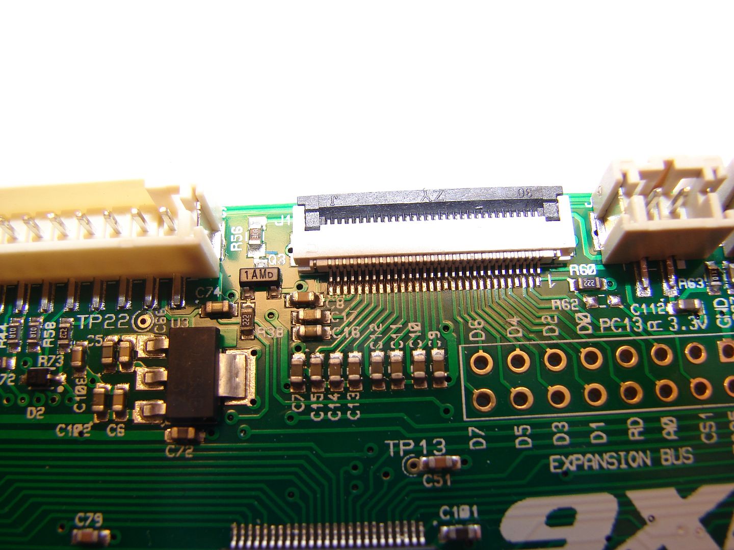
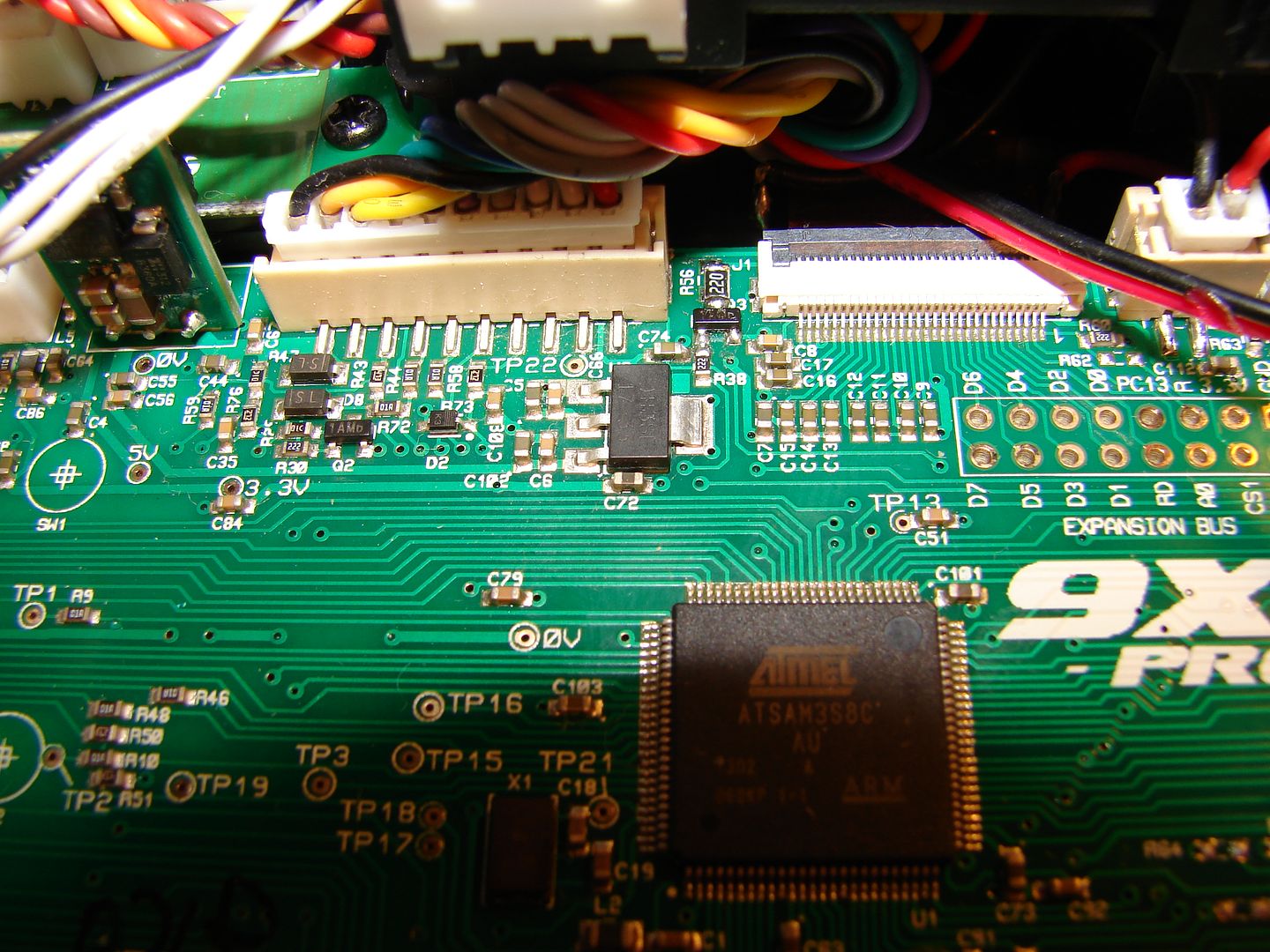
On the stock 200Ω ballast resistor at R56, these will barely light up at all. You'll need 17-22Ω at 1/4W to bring these up to full brightness at 65-80ma for the total array. The closer to 17Ω you get, the brighter Max brightness will be.
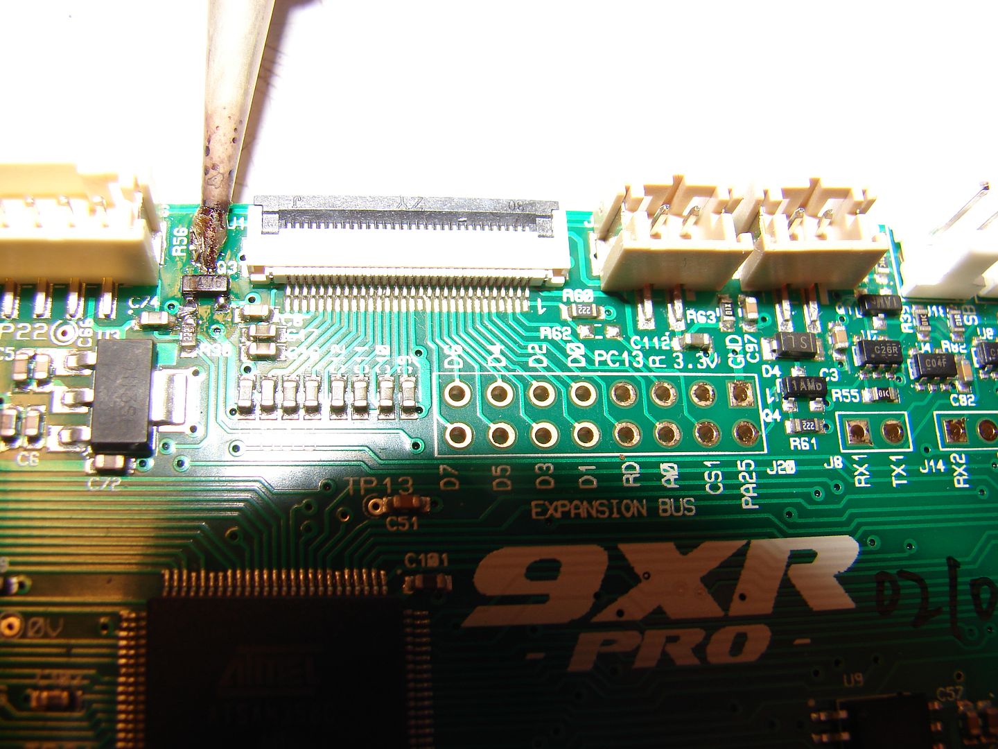
Bridge both ends of R56 with a blob of solder and just wipe it off the pads with the tip of your iron.
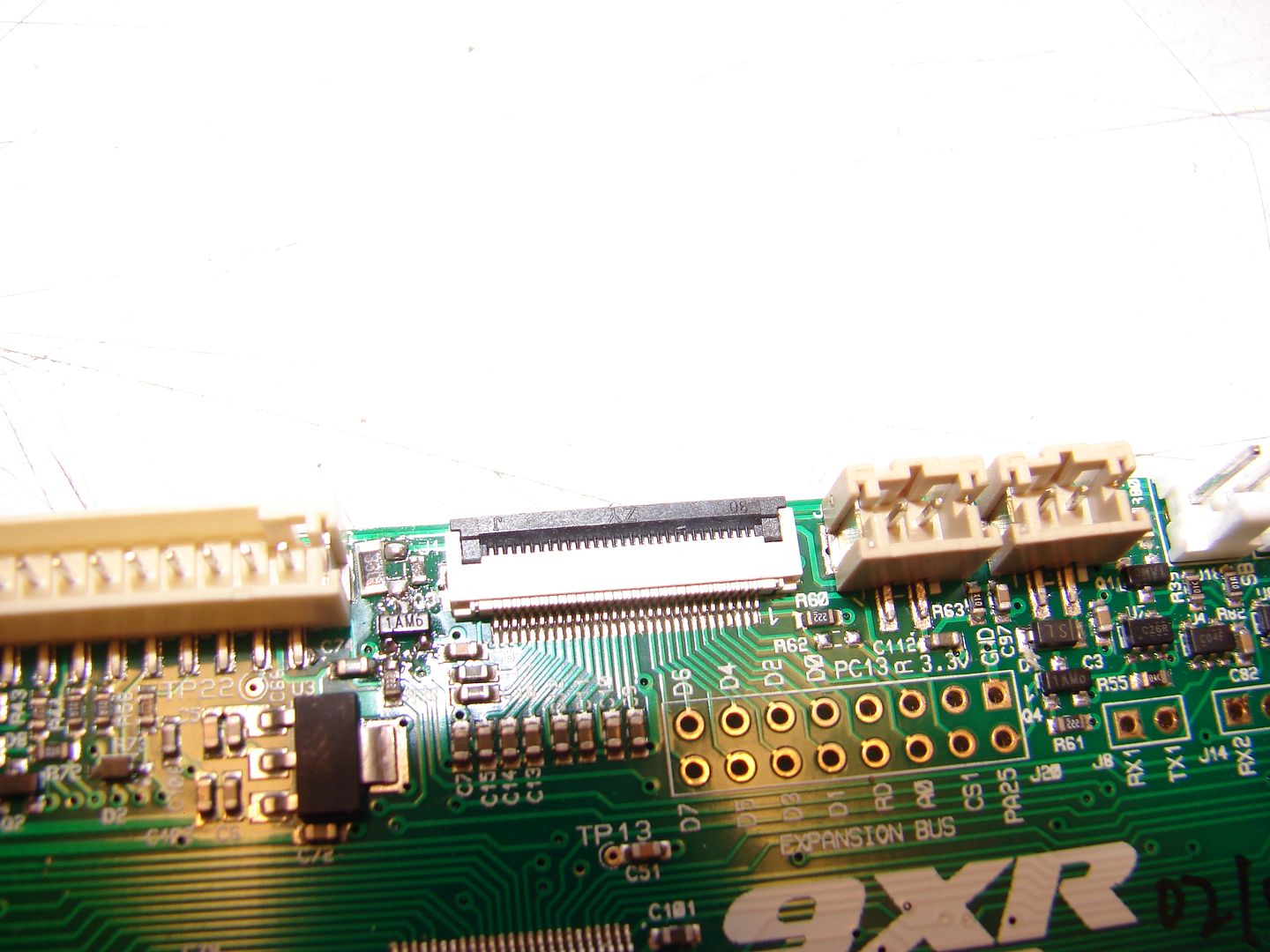
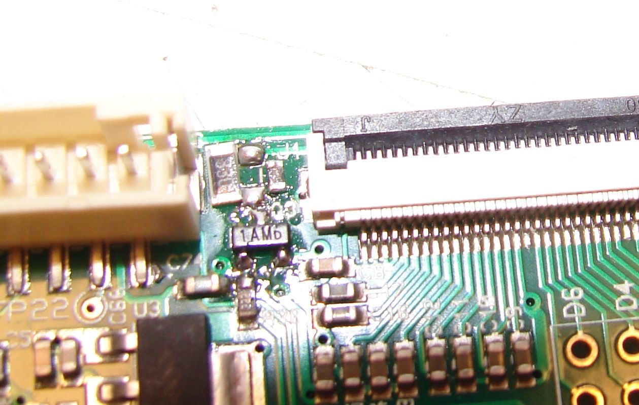
Here's a comparison between the original 1/8W 0805 size resistor and a 1/4W 1206 size 33Ω resistor. As you can see, the 1206 size resistor will fit if we solder one end of it to the pad at the top of Q3. PD here is right on the edge of 1/8W so we really need to have 1/4W of ballast resistor; hence the bump up to 1206 size.
I later switched over to the 22Ω resistor seen here for my OEM Blue Backlight; it drives that at about 14ma per LED. It drives these at 10-11ma each; right about the same brightness as the original 9XR backlight.
I subbed a 17Ω resistor for testing here and it drove these at approx 14mA each; the backlight looks a little less grey and noticeably brighter.
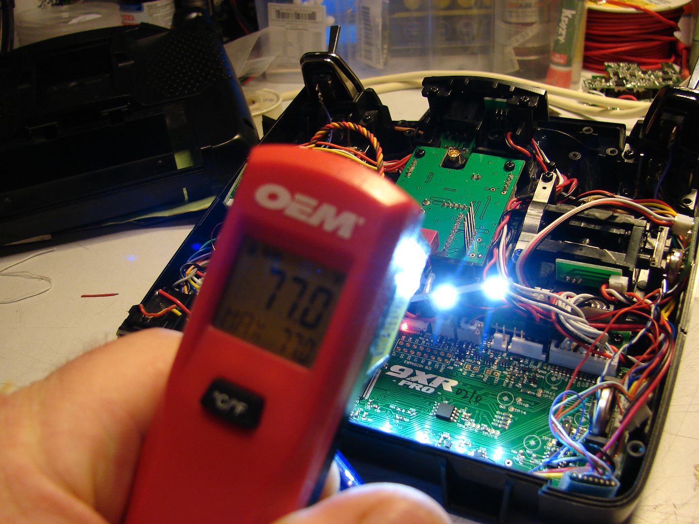
Time to test! Dang those are bright!
But after running over 30 minutes, still room temperature. Excellent! Time to reassemble everything!
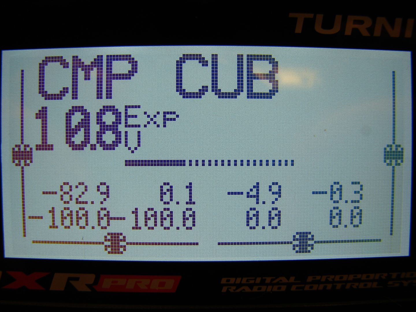
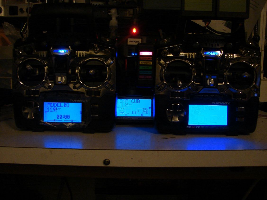
Here's some screen shots of the new brighter, whiter LCD! w00t!
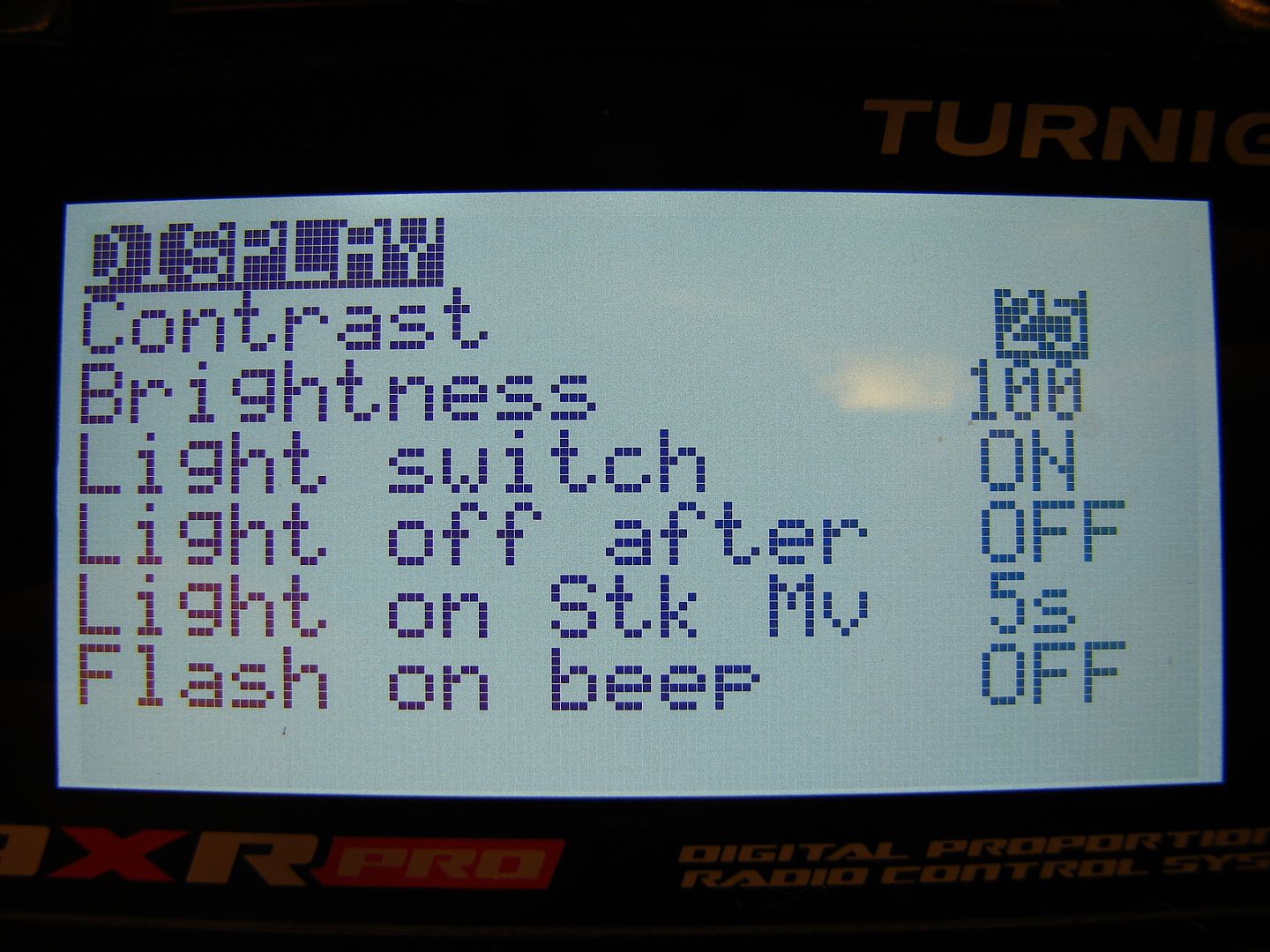
With the White LEDs, the LCD looks a bit better with Contrast cranked up to 25; Other colors will look better at different contrast settings.
Well, that pretty much covers it. Now you know how to put pretty much any color LED you want in the backlight of your 9XR/9XR Pro!
Good Luck!
mnem
Keep Moving Forward.