
G'day,
The camera which came with my WLToys V959 RC quadcopter does a reasonably good job of recording video - audio is of course there but never much to listen to with motors buzzing ...
But lately, I've been flying my Bixler more than the quad and I was thinking about mounting the camera on the Bixler instead - but in order to do that, I need a way to trigger the camera record function (and optionally photo function).
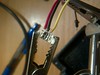
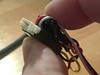
So I did some tinkering and I've managed to find out what the four wires do (as far as I can tell):
red: +5v
black: gnd
yellow: +3.3v nominal, pull to ground for 250ms to start or stop video fuction
white: +3.3v nominal, pull to ground for 250ms to take a still photograph
I think I am OK with powering the camera (BEC?) but I'm not quite sure how to link up RX channels on my 9x (stock) receiver to control the video or optionally the photo function... any suggestions on a simple solution to drive this little camera?
Thanks in advance!
Cheers
Leigh
v959 camera hacking
Re: v959 camera hacking
I can think of a couple of ways to bring 5v down to 3.3 assuming the camera trigger lines won't like being driven at 5v, but I haven't a clue where to start using a channel to trigger the 250ms drop...
Any gurus have any suggestions?
Er9x is the firmware I am using today...
Any gurus have any suggestions?
Er9x is the firmware I am using today...

Re: v959 camera hacking
You'll need some active circuitry between the receiver and camera for sure. There are a couple of microcontroller-based projects like this one:
http://www.rc-cam.com/project1.htm
http://www.rc-cam.com/project1.htm
Re: v959 camera hacking
Thanks for that Kilrah - you got me thinking outside the box there 
I hooked up my Arduino Uno to the 9x RX thusly:
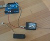
+5V from the Uno to +BAT on the RX
GND from the Uno to -BAT on the RX
Digital Input pin 5 on the Uno to channel 8 SIG on the RX
I then used pulseIn to read the pulses on channel 8 which I had mixed as "CH8 100% FULL GEA" in er9x.
I initially just printed out the values - 1400ish when the gear switch was off, 1900ish when the gear switch was on. I then setup a toggle:
Output from serial monitor was:
[BBvideo 425,350]http://www.flickr.com/photos/allandrick/8509087140/[/BBvideo]
Next step will be to wire up the camera, powered by the Arduino 5V rail, and triggered by way of a voltage divider circuit (5V digital output -> 3.333V camera trigger input) - when the gear switch is pressed, I'll pulse the output of the digital pin LOW for 250ms...
Does this sound like a sensible approach?
If it does, and it works reliably, I'll bung it all into an ATtiny45
I hooked up my Arduino Uno to the 9x RX thusly:
+5V from the Uno to +BAT on the RX
GND from the Uno to -BAT on the RX
Digital Input pin 5 on the Uno to channel 8 SIG on the RX
I then used pulseIn to read the pulses on channel 8 which I had mixed as "CH8 100% FULL GEA" in er9x.
I initially just printed out the values - 1400ish when the gear switch was off, 1900ish when the gear switch was on. I then setup a toggle:
Code: Select all
int channel;
int gear;

void setup() {
  pinMode(5, INPUT);
  Serial.begin(9600);
  Serial.println("Channel reader starting");
  channel = pulseIn(5, HIGH, 20000);
  if (channel > 1600) {
      // gear switch already on when we got power,
      // we will ignore first toggle state
      gear = 2;
  }
  else {
      // gear switch is off
      gear = 0;
  }
}

void loop() {
  channel = pulseIn(5, HIGH, 20000);
  if (channel > 1600 && gear == 0) {
    Serial.println("Gear switch went on");
    gear = 1;
    Serial.print("sending 250ms pulse to camera pin 6...");
    // send video control line to 0V
    delay(250);
    // return video control line to 3.3V
    Serial.println("done!");
    Serial.println("Camera should now be recording.");
  }
  if (channel < 1600 && gear == 1) {
    Serial.println("Gear switch went off");
    gear = 0;
    Serial.print("sending 250ms pulse to camera pin 6...");
    // send video control line to 0V
    delay(250);
    // return video control line to 3.3V
    Serial.println("done!");
    Serial.println("Camera should no longer be recording.");
  }
  if (channel < 1600 && gear == 2) {
    Serial.println("Gear switch went off, ignoring first switch from invalid state.");
    gear = 0;
  }
}[BBvideo 425,350]http://www.flickr.com/photos/allandrick/8509087140/[/BBvideo]
Next step will be to wire up the camera, powered by the Arduino 5V rail, and triggered by way of a voltage divider circuit (5V digital output -> 3.333V camera trigger input) - when the gear switch is pressed, I'll pulse the output of the digital pin LOW for 250ms...
Does this sound like a sensible approach?
If it does, and it works reliably, I'll bung it all into an ATtiny45
Re: v959 camera hacking
Well, good, didn't know you were into arduinos, but yes it's exactly the idea 
A little hint that allows you to get rid of the level converter is to use your arduino's output as open collector: When you need it LOW, then turn it LOW. When you need it high, do NOT turn it HIGH, but switch it to input mode instead. The camera's pull-up will do its job and hold it at 3.3V.
As long as you're careful not to set the pin HIGH you're good.
Re: v959 camera hacking
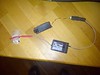
Oh, that will make life a bit easier I've ordered some attiny45 and attiny85 chips and after a bit of googling and micrometer measuring (image search for the win) I found a header connector that looks like it is a match for the socket on the WLtoys V959 flight controller camera port - that way I won't have to hack up the cable connector

I got a heap of servo extension cables (55p each, woo), some of which I'll use in my bixler to allow me to mix my ailerons separately (flaperons, anyone?)
I got a heap of servo extension cables (55p each, woo), some of which I'll use in my bixler to allow me to mix my ailerons separately (flaperons, anyone?)
Re: v959 camera hacking
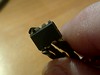
I didn't realize how small these connectors would be - soldering them to some test leads so I could breadboard the prototype on the attiny45 was a nightmare! My eyesight isn't that good - and even with a magnifying glass, I was struggling. Thankfully, the trusty Multimeter confirmed that there was no short circuit... *phew* - the testing begins!
Re: v959 camera hacking
Here's a pair of videos demonstrating the functionality (one from my perspective, one from the WLtoys camera which I am triggering with my er9x gear switch
My crappy filming view:
[BBvideo 425,350]http://www.youtube.com/watch?v=UMKg37Rnx5o[/BBvideo]
WLtoys camera view:
[BBvideo 425,350]http://www.flickr.com/photos/allandrick/8516738330/[/BBvideo]
Credit to the folks at the High-Low Tech group (MIT) for the great article on how to use the Arduino Uno as an AVRISP for the AtTiny45.
Now to package it up without the board (components and cabling soldered to the chip) and try to protect the tiny connector, somehow
(edited the video link as flickr ate my video...)
Re: v959 camera hacking
Phew, that was hard work!
Soldering wires to the end of the molex male socket was a pain in the you-know-what. The ones I got were meant for surface mount boards, so I had to gently bend the bottom lugs up into little pins jutting out from the bottom of the connector - I then used the ends of some breadboard jumper wire with the pins removed from the crimped end, pushing the crimp over the tiny pins on the bottom of the molex plug. I then coaxed solder into the crimp, making a nice secure connection to each pin on the molex plug - heat-shrinking each joint before starting the next. Even with the smallest heatshrink tube, it was a tight squeeze fitting them in the 1mm gap between each pin - thankfully I only needed 3 out of the 4 pins connected (video mode is all I care about, taking still photos is only as good as a single video frame on this camera anyway). I then pushed the wires through the square end of a servo cable shroud and glued it all together in a neat package:
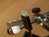
This should remove any possibility of strain being put on the solder joints.
Soldering the wires to the AtTiny45 pins was easy enough - a bit of rosin flux (dispensed by my handy flux pen) followed by a dab of solder on the chip pins, and the solder on the ends of the tinned wires was enough to make a perfect connection without needing too much heat for too long. Six connections later and it was done
I then twisted the wires gently on each end of the circuit and wrapped them around the chip and servo cable shroud for some extra strain relief and got it ready for heatshrink:
Result:
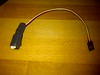
Just like a bought one!
All hooked up ready for installation in my plane:
I tested it and, as with the prototype above, it worked perfectly! I didn't bother adding the LED and resistor, even though the sketch still tries to turn it on, because the camera has an LED status anyway - which was enough for me to confirm I hadn't fried the chip with my soldering efforts nor had I created any shorts between wires in the molex plug end
Happy days!
I'll be shooting some remotely activated video this weekend
Cheers
Leigh
Soldering wires to the end of the molex male socket was a pain in the you-know-what. The ones I got were meant for surface mount boards, so I had to gently bend the bottom lugs up into little pins jutting out from the bottom of the connector - I then used the ends of some breadboard jumper wire with the pins removed from the crimped end, pushing the crimp over the tiny pins on the bottom of the molex plug. I then coaxed solder into the crimp, making a nice secure connection to each pin on the molex plug - heat-shrinking each joint before starting the next. Even with the smallest heatshrink tube, it was a tight squeeze fitting them in the 1mm gap between each pin - thankfully I only needed 3 out of the 4 pins connected (video mode is all I care about, taking still photos is only as good as a single video frame on this camera anyway). I then pushed the wires through the square end of a servo cable shroud and glued it all together in a neat package:
This should remove any possibility of strain being put on the solder joints.
Soldering the wires to the AtTiny45 pins was easy enough - a bit of rosin flux (dispensed by my handy flux pen) followed by a dab of solder on the chip pins, and the solder on the ends of the tinned wires was enough to make a perfect connection without needing too much heat for too long. Six connections later and it was done
I then twisted the wires gently on each end of the circuit and wrapped them around the chip and servo cable shroud for some extra strain relief and got it ready for heatshrink:
Result:
Just like a bought one!
All hooked up ready for installation in my plane:
I tested it and, as with the prototype above, it worked perfectly! I didn't bother adding the LED and resistor, even though the sketch still tries to turn it on, because the camera has an LED status anyway - which was enough for me to confirm I hadn't fried the chip with my soldering efforts nor had I created any shorts between wires in the molex plug end
Happy days!
I'll be shooting some remotely activated video this weekend
Cheers
Leigh

Re: v959 camera hacking
so the atiny45 alone can do the job of converting 5v to 3.3v and switch on and off?
but it needs an arduno to program it right?
but it needs an arduno to program it right?
Re: v959 camera hacking
The attiny45 runs on the 5v input from the receiver but as Kilrah suggested above it doesn't need to convert to 3.3v to switch the camera on and off - it simply drives the output to the camera's video control line low for 250ms to trigger the video to start and stop, but returns the output to an input which seems to let it float at 3.3v (what the camera wants on that line)... I don't really understand how it works, but it seems to do so quite well I'll post a video from on board as soon as it has finished processing.
Re: programming the attiny45 - I used an Arduino Uno as an ISP to program it - but there are other devices which can make life a bit easier such as the Tiny AVR programmer from SparkFun.
Re: programming the attiny45 - I used an Arduino Uno as an ISP to program it - but there are other devices which can make life a bit easier such as the Tiny AVR programmer from SparkFun.
Re: v959 camera hacking
dang, 20 dollar programer to program a 20 dollar cam. hmmm needs to think about it. may be it is good for something later too. I think I have spent more money on buying tools than the actual flying thing. 
Re: v959 camera hacking
Yeah, thankfully I had an Arduino lying around to act as an ISP - so I didn't need to buy the programmer
Re: v959 camera hacking
May be I should buy one programed chip from you and come out cheaper. interested?
Re: v959 camera hacking
Three flights on Sunday with the V959 on the Bixler:
[BBvideo 425,350]http://www.youtube.com/watch?v=cYk6PNpoP2Q[/BBvideo]
[BBvideo 425,350]http://www.youtube.com/watch?v=HmC93X3uOy0[/BBvideo]
[BBvideo 425,350]http://www.youtube.com/watch?v=DFMsy7fSjrU[/BBvideo]
[BBvideo 425,350]http://www.youtube.com/watch?v=cYk6PNpoP2Q[/BBvideo]
[BBvideo 425,350]http://www.youtube.com/watch?v=HmC93X3uOy0[/BBvideo]
[BBvideo 425,350]http://www.youtube.com/watch?v=DFMsy7fSjrU[/BBvideo]
Re: v959 camera hacking
for a 20.00 vid cam , not bad at all. Now all you need is to hook it up to a vid tx and get a goggle to fly FPV.
was that recorded with on board recorder?
was that recorded with on board recorder?
Re: v959 camera hacking
Can't you just use any avr programmer like the usbasp you should have?
Sent via mobile
Sent via mobile
Re: v959 camera hacking
that will make everything backwards. the programmer I am supposed to get soon will stay in the tx. now I have to convert the SP to attached some header to become a programmer. 
Isn't SP supposedly solder free and plug and play.
Isn't SP supposedly solder free and plug and play.
Re: v959 camera hacking
Any updates to this?
I have a v959 with a fried control board. I'm therefore looking at reusing the video camera on a scratch build plane.
Have you considered implementing the pull-to-ground using a circuit instead of an arduino? I wonder if it wouldn't be just as easy using a capacitor somehow to do this. I don't mind doing this with an arduino, as a I've got a few spare arduino nanos that would do this well. Also I can use it to put some flashing lights or neopixels on too.
Re: v959 camera hacking
Apologies for the absence - I've been rather busy with work and home life recently and other RC projects - I'm fairly sure you could do it with a pull-down circuit triggered by an RC channel somehow - but I'm not really an electronics expert - I know just enough to be dangerous with my Arduino projects

Re: v959 camera hacking
That makes two of us thenhart wrote:I know just enough to be dangerous with my Arduino projects
Welcome back.
João
My er9x/Ersky9x/eepskye Video Tutorials
https://www.youtube.com/playlist?list=PL5uJhoD7sAKidZmkhMpYpp_qcuIqJXhb9
Donate to Er9x/Ersky9x:
https://www.paypal.com/cgi-bin/webscr?cmd=_s-xclick&hosted_button_id=YHX43JR3J7XGW
https://www.youtube.com/playlist?list=PL5uJhoD7sAKidZmkhMpYpp_qcuIqJXhb9
Donate to Er9x/Ersky9x:
https://www.paypal.com/cgi-bin/webscr?cmd=_s-xclick&hosted_button_id=YHX43JR3J7XGW

Re: v959 camera hacking
Very cool Hart, amazing really... contemplating now to do one for myself..
I don't know if I should thank you or not....
Cheers.
I don't know if I should thank you or not....
Cheers.
Custom 9x with M64/Telemetry Mod
Re: v959 camera hacking
Here's what I did with my evening... I connected my receiver and camera to a Nano.

For the camera connector I was 'lucky'. Since I already fried one receiver board from the v959 I was able to pull off the four pin connectors from the board. From the connector I yanked out the existing pins. I sanded down some solid wire and fed it through the pin holes, then used some Instamorph to secure the wires in place and provide a handy grip.

On the transmitter I setup my trainer switch as a camera button. Since it is spring loaded it is acts like a momentary pushbutton. One of the switches became my button for turning on the video. The intention is that when the switch is up the video is recording, and when it is down it is off.
I wrote some fresh code, this time using interrupts to capture the pwm. This allows me to do some other things in my code and have two switches. However at the moment the video is turning on and turning off a second later, and I've not figured out why. Are you sure that video needs a 250ms pulse to turn on and another to turn off? Tomorrow I'll break out my oscilloscope and see if I can identify what is really happening. Once the code is fixed I'll post it in its entirety.
After that I want to move all the wiring to an Adafruit Trinket. Small, but it should be enough for me to run the camera and attach a few lights too.
For the camera connector I was 'lucky'. Since I already fried one receiver board from the v959 I was able to pull off the four pin connectors from the board. From the connector I yanked out the existing pins. I sanded down some solid wire and fed it through the pin holes, then used some Instamorph to secure the wires in place and provide a handy grip.
On the transmitter I setup my trainer switch as a camera button. Since it is spring loaded it is acts like a momentary pushbutton. One of the switches became my button for turning on the video. The intention is that when the switch is up the video is recording, and when it is down it is off.
I wrote some fresh code, this time using interrupts to capture the pwm. This allows me to do some other things in my code and have two switches. However at the moment the video is turning on and turning off a second later, and I've not figured out why. Are you sure that video needs a 250ms pulse to turn on and another to turn off? Tomorrow I'll break out my oscilloscope and see if I can identify what is really happening. Once the code is fixed I'll post it in its entirety.
After that I want to move all the wiring to an Adafruit Trinket. Small, but it should be enough for me to run the camera and attach a few lights too.
Re: v959 camera hacking
My error was due to some bad debugging.
In any case here is the code I used. I haven't moved it to the Trinket / ATTiny85 yet. I think the Trinket will support only one pin for interrupt and I have two pins for the two controls. What I would like to do instead is implement this using something that reads from the data ppm pin instead so I can capture all pins with one interrupt. Won't be today though.
Hope this helps someone.
Code: Select all
#define vidIntPin 2
#define picIntPin 3
#define vidPin 5 // yellow
#define picPin 4 // white


volatile unsigned long vidIntStart = 0; // Set in the interrupt
volatile boolean vidReady = false; // Set in the interrupt and read in the loop
volatile int vidPwmLength = 0;

volatile unsigned long picIntStart = 0; // Set in the interrupt
volatile boolean picReady = false; // Set in the interrupt and read in the loop
volatile int picPwmLength = 0;

boolean takingVideo = false;
boolean takingPhoto = false;

void setup()
{
  attachInterrupt(vidIntPin-2, readVideoPin, CHANGE);
  attachInterrupt(picIntPin-2, readPicPin, CHANGE);

  pinMode(vidPin, INPUT); // Set pins to safe values
  pinMode(picPin, INPUT);

//  Serial.begin(9600);
//  Serial.println("RC camera capture");
}

void loop()
{
//  if (picReady) {
//    Serial.print("picPwmLength ");
//    Serial.println(picPwmLength);
//  }

//  if (vidReady) {
//    Serial.print("vidPwmLength ");
//    Serial.println(vidPwmLength);
//  }

  if (picReady && picPwmLength > 1500 && !takingPhoto) {
//    Serial.println("Triggered photo");
    takingPhoto = true;
    takePic();
  }
  else if (picReady && picPwmLength < 1001) {
    takingPhoto = false;
  }

  if (vidReady && vidPwmLength > 1500 && takingVideo == false) {
//    Serial.println("Triggered video on");
    takingVideo = true;
    takeVid();
  }
  else if (vidReady && vidPwmLength < 1001 && takingVideo) {
//    Serial.println("Turn off video");
    takeVid();
    takingVideo = false;
  }

  picReady = false;
  vidReady = false;
}

void readVideoPin()
{
  if (digitalRead(vidIntPin) == HIGH) {
    vidIntStart = micros();
  }
  else {
    if (vidIntStart && !vidReady)
    {
      vidPwmLength = (int)(micros() - vidIntStart);
      vidIntStart = 0;
      vidReady = true;
    }
  }
}

void readPicPin()
{
  if (digitalRead(picIntPin) == HIGH) {
    picIntStart = micros();
  }
  else {
    if (picIntStart && !picReady)
    {
      picPwmLength = (int)(micros() - picIntStart);
      picIntStart = 0;
      picReady = true;
    }
  }
}

void takeVid() {
//  Serial.println("Turning on/off video");
  pinMode(vidPin, OUTPUT);
  digitalWrite(vidPin, LOW);
  delay(250);
  pinMode(vidPin, INPUT);
}

void takePic() {
//  Serial.println("Taking photo");
  pinMode(picPin, OUTPUT);
  digitalWrite(picPin, LOW);
  delay(250);
  pinMode(picPin, INPUT);
}Re: v959 camera hacking
That's really cool!
Re: v959 camera hacking
I redid this using a Trinket and only just the video lead. However I decided that was more messy than I wanted and also overkill.
I took out the Arduino altogether. Instead I have a single button and four wires.
Camera red <--> positive terminal on receiver
Camera black <--> negative terminal on receiver
Camera Yellow <--> one end of the button
other end of button <--> a second negative terminal on receiver
Push the button and the video starts / red flashing light. Push the button again and the video ends / green light. It was pretty nice to be able to start and stop the video from my radio, but in the end I'll almost always want to start recording from takeoff.
Re: v959 camera hacking
Re: v959 camera hacking
Hello,
i saw that you all are good hackers for that camera..
I've a problem and if someone can help...
My camera started to record flipped movies and pictures for 180 degrees. At the beginning was all ok, some how(I do not how) it flipped picture?
I know that some cameras have (mobius or key chain) config file for SD card. I hope that this is the same with that cam or it have some shortcut for settings with remote or something...
Did someone come across the same problem? or. can anyone know how to resolve my problem to flip picture around?
Thank you for your kindness!
regards,
monsi
Re: v959 camera hacking
Hello, did anyone have the same problem? Please, help. It was a gift and now it wont work..
Re: v959 camera hacking
You can just turn it around in Windows Movie Maker or the like or mount the camera upside down at a pinch. I don't know of anyway to access the SD config file like with the Mobius