Hi all, I did a ton of reading before buying parts and modding and I can't figure out what step I'm missing.
I installed the DJT module and have the D8R-IIplus receiver. I went ahead and wired it up just like this:
http://openrcforums.com/wiki/index.php/ ... y_Lite.jpg
And moved the switches off the Mosi and Miso pins then wired up a usbasp and installed er9x-FRSKY with eePe.
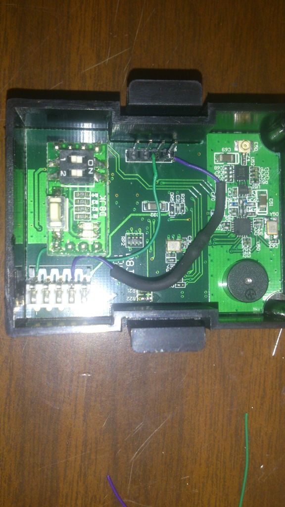
Inside the RF module
Re-routed switches
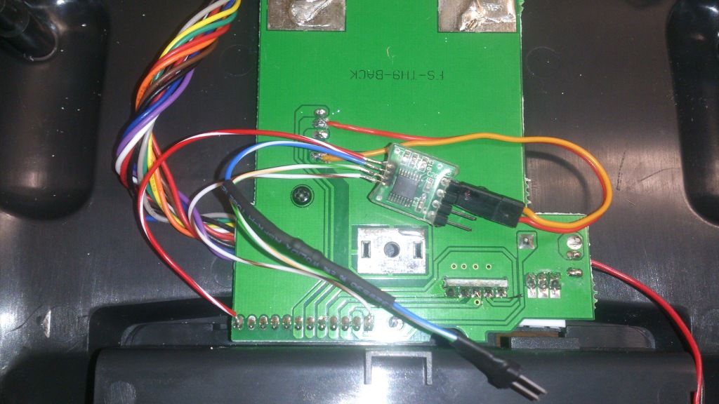
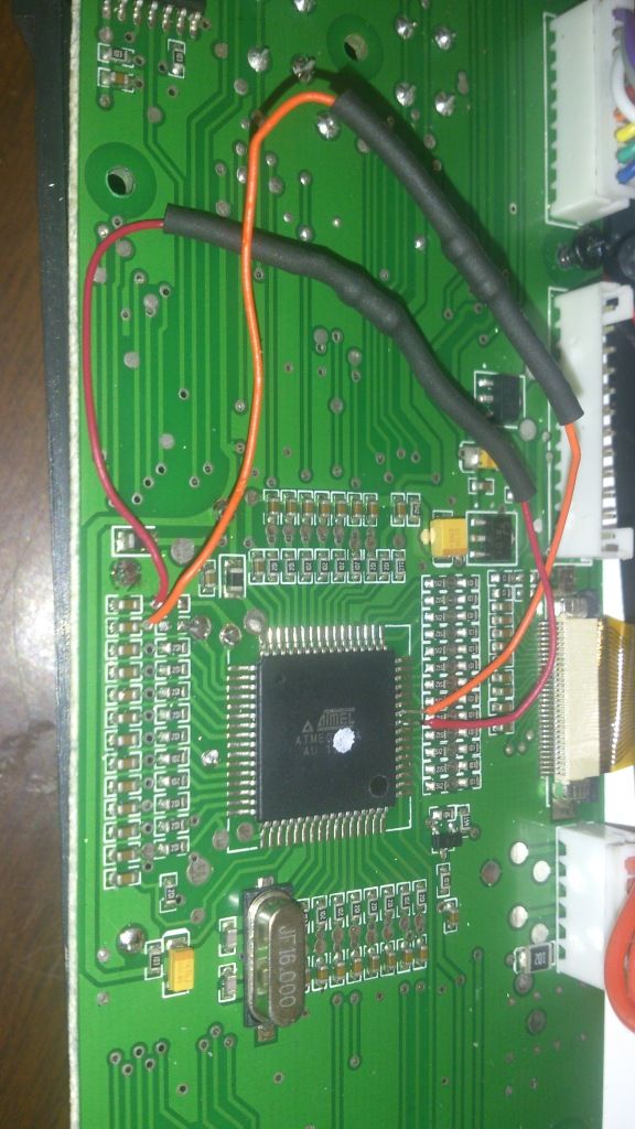
Level shifter wired as described in first link
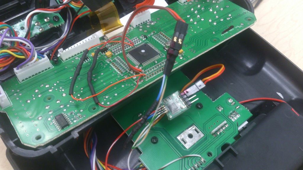
All connected
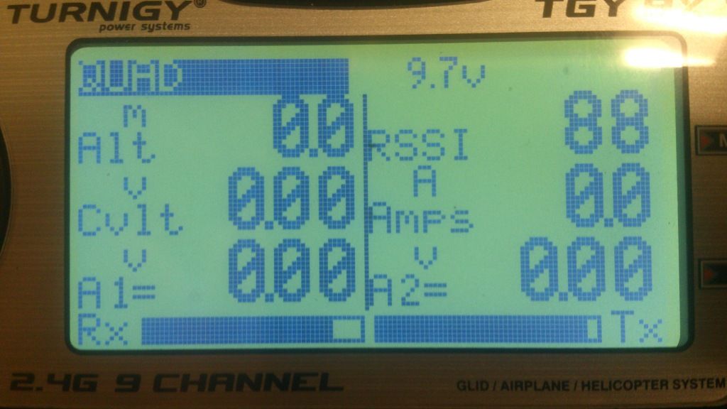
I am getting the Rx and Tx values on the screen - so it is binded and communicating but I can't get anything else to show up with telemetry. I read A2 should show the Rx voltage with jumper between A2 and x. I also connect A1 to 5V and no data on the screen. I am trying to use j-drones IOboard firmware with Arduino nano to send the mavlink packets from Arducopter but no other data shows up.
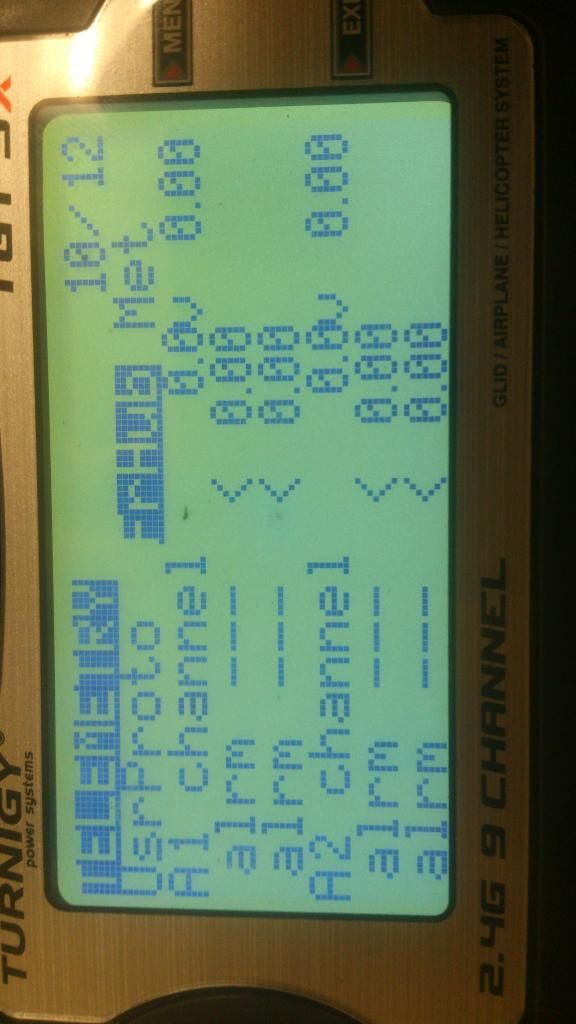
In the Telemetry menu I can switch between FrHub and WSHhi but neither work. Should the A1 and A2 values be shown on this Telemetry menu? I set custom display to A1 and A2 but all values show zero on main screen (pressing down once).
Hopefully just one simple setting I'm missing?
Thanks!
Did the mods but telemtry isn't working - help
-
- Posts: 13
- Joined: Tue Sep 10, 2013 1:20 pm
- Country: -
Re: Did the mods but telemtry isn't working - help
You have to set the range of A1 and A2.
For example if you use the internal voltage sensor for A1 you have to set it to 13.2V.
It's working because you have RSSI
And remember: never put higher voltages then 3.3V on A1 or A2.
For example if you use the internal voltage sensor for A1 you have to set it to 13.2V.
It's working because you have RSSI
And remember: never put higher voltages then 3.3V on A1 or A2.
-
- Posts: 13
- Joined: Tue Sep 10, 2013 1:20 pm
- Country: -
Re: Did the mods but telemtry isn't working - help
Sorry guys, photobucket is absolutely refusing to rotate my pictures.
Quick update- I changed the numbers to on the left from 0.00 to 5.00 and now I am getting values from the Rx.
So I guess that means all the mods on my Tx are working and I can close 'er up?
I just need to figure out how to get jdrones IOboard on the nano working?? Is there a setting for this?
I know my data is good because I am connected to Mission planner through XBee.
DIN on Xbee pin is connected to Rx on nano and all data to Mission planner stops... I don't know why.
I have a real IOboard from jdrones coming so maybe I just need to wait for it...
-
- Posts: 13
- Joined: Tue Sep 10, 2013 1:20 pm
- Country: -
Re: Did the mods but telemtry isn't working - help
Thanks for the quick response! It seems I got that working although I was putting 5V on the pins but it seems okay still. Now I'm having trouble getting the MavLink info.NI0X wrote:You have to set the range of A1 and A2.
For example if you use the internal voltage sensor for A1 you have to set it to 13.2V.
It's working because you have RSSI
And remember: never put higher voltages then 3.3V on A1 or A2.
Could you explain (or maybe just link me?) what the "range" values actually do? Is it just a linear multiplier for the 0-3.3V on the pin? So when set to 13.2v, 3.3v on the pin will display 13.2v on the screen?
Re: Did the mods but telemtry isn't working - help
You Need a voltage divider if you want to use voltages higher then 3.3V.
The intern voltage divider is Ratio 4 to 1, so 4 * 3.3 = 13.2. If you put in 13.2 the voltage divider puts out 3.3, so 13.2V is Maximum for 4:1.
You can build your own voltage divider with 2 resistors and one capacitor.
The intern voltage divider is Ratio 4 to 1, so 4 * 3.3 = 13.2. If you put in 13.2 the voltage divider puts out 3.3, so 13.2V is Maximum for 4:1.
You can build your own voltage divider with 2 resistors and one capacitor.
- ShowMaster
- Posts: 4327
- Joined: Thu Dec 29, 2011 3:44 am
- Country: -
- Location: Los Angeles, CA USA
Did the mods but telemtry isn't working - help
Make U2 3.3v and U1 your lipo voltage.
calculator.html http://tuxgraphics.org/toolbox/circuit- ... lator.html