First off, check FU1 and R9 on the BACK board. R9 is 0.1 ohms and is used to measure the current in use by the Tx. If the power gets overloaded, this does tend to overheat and blow open circuit.
Mike.
erskyTx/er9x developer
The difficult we do immediately,
The impossible takes a little longer!
MikeB wrote:First off, check FU1 and R9 on the BACK board. R9 is 0.1 ohms and is used to measure the current in use by the Tx. If the power gets overloaded, this does tend to overheat and blow open circuit.
MikeB wrote:First off, check FU1 and R9 on the BACK board. R9 is 0.1 ohms and is used to measure the current in use by the Tx. If the power gets overloaded, this does tend to overheat and blow open circuit.
Can you confirm you connected 5V to the mainboard and the radio worked? If so, I believe you might have a bad 5V regulator.. it's that little board standing at the top of the mainboard on the left hand side.. But let's wait and see what Mike says..
João
My er9x/Ersky9x/eepskye Video Tutorials
https://www.youtube.com/playlist?list=PL5uJhoD7sAKidZmkhMpYpp_qcuIqJXhb9
Donate to Er9x/Ersky9x:
https://www.paypal.com/cgi-bin/webscr?cmd=_s-xclick&hosted_button_id=YHX43JR3J7XGW
The pin you have as 2.78 to 4.54v should be the battery voltage.
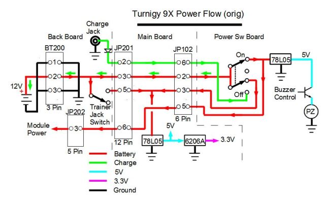
The batter is connected first to FU1, then R9, then goes to pins 2 and 3 of J5 on the back board. The power switch then switches the power from pin 2 to pin 5 of J5 and from pin 3 to pin 1 of J5. Pin 1 of J5 supplies the RF module via D4. Pin 5 of J5 supplies the power, via D2, to the main board.
So perhaps trace the voltage from the battery at FU1, R9, pins 2 and 3 of J5, all of which can be done with the power switch OFF.
Then repeat with the power switch ON, and follow through to pins 1 and 5 of J5, D2 and pin 10 of the 10 way connector.
Mike.
erskyTx/er9x developer
The difficult we do immediately,
The impossible takes a little longer!
jhsa wrote:Can you confirm you connected 5V to the mainboard and the radio worked? If so, I believe you might have a bad 5V regulator.. it's that little board standing at the top of the mainboard on the left hand side.. But let's wait and see what Mike says..
João
I connect 5v to the mainboard and the radio power on.
and put on display
shutting down
power off
In the video looks bad the text, but actually looks normal
MikeB wrote:The pin you have as 2.78 to 4.54v should be the battery voltage.
The batter is connected first to FU1, then R9, then goes to pins 2 and 3 of J5 on the back board. The power switch then switches the power from pin 2 to pin 5 of J5 and from pin 3 to pin 1 of J5. Pin 1 of J5 supplies the RF module via D4. Pin 5 of J5 supplies the power, via D2, to the main board.
So perhaps trace the voltage from the battery at FU1, R9, pins 2 and 3 of J5, all of which can be done with the power switch OFF.
Then repeat with the power switch ON, and follow through to pins 1 and 5 of J5, D2 and pin10 of the 10 way connector.
Mike.
Thankss Mike
all green is ok, in D4 and D2 have 11.28v and the voltage at pin 10 of the 10 way connector is correct (11.24v) when the connector is removed from the main board.
when i connect the 10 way connector (j3) to the main board the voltage oscilate 2.78v to 4.54v
also i try to check with only connect in the back board the J5 and J3 connector with the same results
Please confirm you are saying that when all is plugged in, and when you switch on, you still have the battery voltage at FU1, R9, pins 2 and 3 of J5, and at pins 1 and 5 of J5 and D2, but not at pin 10 of the 10-way connector on the back board.
If you have the battery voltage at FU1, but this 2.78-4.54V on the main board, we should be able to locate where the voltage is dropping.
Mike.
erskyTx/er9x developer
The difficult we do immediately,
The impossible takes a little longer!
MikeB wrote:Please confirm you are saying that when all is plugged in, and when you switch on, you still have the battery voltage at FU1, R9, pins 2 and 3 of J5, and at pins 1 and 5 of J5 and D2, but not at pin 10 of the 10-way connector on the back board.
If you have the battery voltage at FU1, but this 2.78-4.54V on the main board, we should be able to locate where the voltage is dropping.
Mike.
when 10-way connector unplugged all voltage is ok
when 10-way connector plugged the battery voltage at FU1 is ok, in R9 imput is ok, R9 output loss the voltage
sorry translate mistake
Last edited by davidluab on Fri Oct 09, 2015 3:35 pm, edited 3 times in total.
Seems like R9 is not right. It should be 0.1 ohms.
1. Please measure the resistance of R9.
2. Please check very carefully it is fully soldered on both sides.
3. You may short R9 out with a piece of wire. All you will lose is the Tx current measurement.
Mike.
erskyTx/er9x developer
The difficult we do immediately,
The impossible takes a little longer!
MikeB wrote:Seems like R9 is not right. It should be 0.1 ohms.
1. Please measure the resistance of R9.
2. Please check very carefully it is fully soldered on both sides.
3. You may short R9 out with a piece of wire. All you will lose is the Tx current measurement.
Mike.
Thanks Mike.
I check the R9 and the resistance is about 100 ohms.
If you make zoom in my picture, you can read the valure of the resistance.( 100 ohms)
MikeB wrote:Seems like R9 is not right. It should be 0.1 ohms.
1. Please measure the resistance of R9.
2. Please check very carefully it is fully soldered on both sides.
3. You may short R9 out with a piece of wire. All you will lose is the Tx current measurement.
Mike.
Thanks mike, i short R9 and appears to work well, I will buy a resistor 0.1 ohms , and later check all
Just leave R9 shorted out until you can get a correct value resistor. You only lose the monitoring of the transmitter current, which doesn't cause any real problems.
Mike.
erskyTx/er9x developer
The difficult we do immediately,
The impossible takes a little longer!