hk backlight mod

General mods that are considered worth doing; regardless of the end firmware you use.
41south
Posts: 2
Joined: Tue Aug 07, 2012 2:03 am
Country: -

Re: hk backlight mod

Post by 41south »

Hi all,

I just fitted the Smartieparts v2.2 board and HK blue BL to my 9x and I'm underwhelmed by the difference with the BL to say the least :( I'm test running it off a 7.4v lipo at this stage, should I be changing some resistors somewhere to beef up the brightness? I need to put this thing into a dark closet just to see that it's on :lol:

Thanks
Colin.

User avatar
flashbang
Posts: 59
Joined: Sat Apr 07, 2012 4:18 pm
Country: -
Location: USA NY

Re: hk backlight mod

Post by flashbang »

Hi all,
Is there any proven off the shelf transistors from RadioShack that will work for this mod?
TIA
User avatar
ShowMaster
Posts: 4327
Joined: Thu Dec 29, 2011 3:44 am
Country: -
Location: Los Angeles, CA USA

Re: hk backlight mod

Post by ShowMaster »

A 2N3904 is very a common NPN and should be in stock
http://m.radioshack.com/radioshack/prod ... yId=&path=
Where do you live?
There may be a local source for the 2n7000 FET or the BC170.


ShowMaster
Sent from my iPod touch using Tapatalk
41south
Posts: 2
Joined: Tue Aug 07, 2012 2:03 am
Country: -

Re: hk backlight mod

Post by 41south »

As far as I know this revision of the board needed no other mods or components - did I miss something ??

My question related to the latest Smartieparts 2.2 bd.

Thanks
User avatar
gohsthb
Posts: 1412
Joined: Wed Dec 28, 2011 2:32 pm
Country: -
Location: Naperville, IL

Re: hk backlight mod

Post by gohsthb »

http://www.smartieparts.com/shop/index. ... cts_id=331

It says it hs support for it, however I don't know what that means.
-Gohst

j0bro
Posts: 23
Joined: Thu Jul 05, 2012 9:34 am
Country: Netherlands
Location: Eindhoven

Re: hk backlight mod

Post by j0bro »

You probably put the BL in upside down! Only one side illuminates, follow the SP installation instructions closely.
I have the white BL and it definitely makes a big difference in readability.
User avatar
MikeB
9x Developer
Posts: 17993
Joined: Tue Dec 27, 2011 1:24 pm
Country: -
Location: Poole, Dorset, UK

Re: hk backlight mod

Post by MikeB »

41south: As I understand it the V2.2 SP board uses the control signal upside down compared to other BL implementations. The last couple of revisons of er9x have an option to allow for this. Itis possible yo haven't actually got the Bl turned ON.

Mike.
erskyTx/er9x developer
The difficult we do immediately,
The impossible takes a little longer!
User avatar
ShowMaster
Posts: 4327
Joined: Thu Dec 29, 2011 3:44 am
Country: -
Location: Los Angeles, CA USA

Re: hk backlight mod

Post by ShowMaster »

Oops, newer SP board. OK, driver on board fet already. Missed that.


ShowMaster
Sent from my iPod touch using Tapatalk
User avatar
flashbang
Posts: 59
Joined: Sat Apr 07, 2012 4:18 pm
Country: -
Location: USA NY

Re: hk backlight mod

Post by flashbang »

ShowMaster wrote:A 2N3904 is very a common NPN and should be in stock
http://m.radioshack.com/radioshack/prod ... yId=&path=
Where do you live?
There may be a local source for the 2n7000 FET or the BC170.


ShowMaster
Sent from my iPod touch using Tapatalk
I can get this part, but what would the correct conversion be for the pin out since the 2n3904 has a Emitter, Base and Collector?
Is this correct:
Connect the Collector where the Drain would go, the Emitter where the Source would go, and the Base where the Gate would go?

Any truth to this:
With the bipolar transistor you would need at least a 1K resistor in between the base of the transistor and the output pin on the ATMEGA.
TIA
User avatar
MikeB
9x Developer
Posts: 17993
Joined: Tue Dec 27, 2011 1:24 pm
Country: -
Location: Poole, Dorset, UK

Re: hk backlight mod

Post by MikeB »

Yes, a FET gate is driven by a voltage so doesn't need a resistor, while a bipolar transistor is driven by current so MUST have a resistor, 1K is quite low in value, I'd use 4K7 to 10K.

Mike.
erskyTx/er9x developer
The difficult we do immediately,
The impossible takes a little longer!
mambamax1
Posts: 30
Joined: Wed Aug 01, 2012 9:24 pm
Country: -

Re: hk backlight mod

Post by mambamax1 »

To save from using one of the radio's switches, I'd like to use a separate toggle switch for the light. In this case, would I just need a switch that can handle 12v? Also, would I just solder it in-line with the positive and negative wire of the BL?

Also, would a 270 ohm resistor be a good choice to increase brightness since I'm only using a 2s lipo? How low of a value is too low for the resistor?
User avatar
ShowMaster
Posts: 4327
Joined: Thu Dec 29, 2011 3:44 am
Country: -
Location: Los Angeles, CA USA

Re: hk backlight mod

Post by ShowMaster »

I believe 270 will put you over 20 Ma max on fully charged battery. You may want to use a 330 ohm. This should e good for 7.2 also. You could use a 500 ohm to set the max current to 20 ma full charge max and measure the value you come up with for your final value. I thought how ever the new SP board has a current limiting circuit that's pretty neat.
There was a post with a circuit like that that adjust to the battery voltage applied and is a good way to go. May e someone has that link and may its good to put into wiki?
For quick and dirty the 270-330 ohm resistor a d a mini toggle is a way to go and has been done before and posted. Maybe on RCG last year?
I like the current limiting circuit idea and will search for it now that we've discussed it for my notes. The ersky9x board used PWM to drive the LEDs so they're pulsed and can take a higher current due to the short duty cycle I think I read. I still added some R to limit current at the install time so I never got the final value nailed down but it works.


ShowMaster
Sent from my iPod touch using Tapatalk
User avatar
Daryoon
Posts: 60
Joined: Sun Jan 08, 2012 5:07 pm
Country: -
Location: http://www.hacksmods.com
Contact:

Re: hk backlight mod

Post by Daryoon »

The HobbyKing backlight has both side with a thin white plastic. To tell which side needs to face down, look for the side with a clear protective film on it. I suspect many people miss this thin film and probably leave it on when they install the backlight kit.

I remove that clear plastic film and install that side face down. I also only use 100ohm resistor for the blue and white backlight. I connect it to the 5v output on the main board as demonstrated by one of the user above. Works like a charm so far and easier to do thank modifying that pass through board. You gain a couple of 6pin connectors in the process, which I use as programming ports for the USBASP.
User avatar
flashbang
Posts: 59
Joined: Sat Apr 07, 2012 4:18 pm
Country: -
Location: USA NY

Alternate backlight mod W/Radioshack 2N3904

Post by flashbang »

Thanks for all the help. Trying to give back and help others out.
Went ahead with the RadioShack 2N3904 NPN Small Signal Transistor route.
All parts can be had for about 4USD [Not including the back light] and the best part, found locally.

I cut the PCB off the Hobby King back light which frees up space, clutter and leaves you with just the two wires coming off the back light. One red and one black. I chose to get the 5V source right off the main board of the 9x along with the ground.
I used a 4K7 Ohm resistor in-line from pin 17 of the MCU and the Base of the 2N3904,
A 220 Ohm resister on the positive [red] wire of the back light to the 5v source on the main board.
The negative [black] wire from the back light to the Collector of the 2N3904
The ground on the main board to the Emitter of the 2N3904

Works great on the Blue HK back light. Brighter than the EL I had and maybe you can go brighter by using a lower value resistor on the red wire of the back light. Thanks to all who helped and I hope this helps anyone out looking to do this mod without a BS170 or FET and not wishing to order one.
I have a diagram I shamelessly stole and altered. I would give credit if I knew who made it. Anyway it may be good to add it to the wiki page so it can be viewed by all with the addition of the 2N3904 NPN Small Signal Transistor.
Attachments
Backlight-switch-circuit.jpg
User avatar
ShowMaster
Posts: 4327
Joined: Thu Dec 29, 2011 3:44 am
Country: -
Location: Los Angeles, CA USA

Re: hk backlight mod

Post by ShowMaster »

Good 2N3904 install description.
Thanks


ShowMaster
Sent from my iPod touch using Tapatalk
User avatar
algo
Posts: 117
Joined: Sun Sep 02, 2012 3:11 pm
Country: -

Re: hk backlight mod

Post by algo »

Sorry I haven't read the whole thread (what's wrong with the forum? :() and maybe this has been discussed.

I just tested my HK backlight and it pulls less than 5mA at 5V with a 470 ohm resister. Seems to me that it can just be driven directly with pin 17, no?

I removed the wiring harness and my plan is to connect the backlight directly to the board. Ground to one of those ground pads near the harness and then positive through a 470 ohm resister directly to pin 17.

I mean I know this would normally be no problem on an ATmega but is the whole chip so loaded that it can't handle an extra 5mA? Is there a reason why the wiki says to use a MOSFET? Unless it's just to be extra safe in case someone uses a high power light? Or is it switching power directly from the battery for a brighter light? 5V is bright enough for me.
User avatar
ShowMaster
Posts: 4327
Joined: Thu Dec 29, 2011 3:44 am
Country: -
Location: Los Angeles, CA USA

Re: hk backlight mod

Post by ShowMaster »

I think the FET is used because its gate needs no current limiting resistor. The transistor switch does. There was some time ago someone that did run his BL directly from pin 17 I think. I'm surprised that you were happy with the brightness of 5ma. There is the risk of damaging the m64 and so I think the FET offered the lowest current drive and isolation.

The BL as it comes is designed to run off of the tx battery source and that can be as much as 12v or as low as 7.4v
I posted this many months ago as a voltage vs current vs brightness. It may help?

*
HK White Backlight current draw vs. voltage applied 5-13V.
The stock backlight has 2 leds with a 470 ohm resistor to limit current.

TX battery voltage/current draw.
5V = 5Ma
6V =7Ma
7V = 9Ma
7.4V = 9.8Ma
8V = 11Ma
9V = 13Ma
9.6V = 14.25Ma
10V = 15Ma
11V = 17Ma
12V = 19Ma
12.6V = 20Ma
13v = 21Ma
Brightness of the backlight does depend on TX battery voltage used. The brightness at 7.4V was more like the stock EL on the SP board. At 9.6V to 12.6V the brightness was much brighter. 12 volts was a little brighter than 9.6-10V but the current went up to 20Ma. I use a LiFe 9.6 volt HK battery so I’m going to use 14.25Ma as my final current constant. My metering of course may have some difference in accuracy but should be close enough for most.
For those using a 2 cell 7.4 type battery setup you may want to lower the 470 ohm resistor to allow the current to be 14Ma as the brightness increase is noticeable.
Hope this helps settle the current draw questions we all had.
If you install this BL note that a circuit board wiring error exists that stops the Trainer out/Simulator PPM signal from working. It requires a circuit trace to be cut and a jumper to be added.
http://www.rcgroups.com/forums/showpost ... ount=12455


ShowMaster
Sent from my iPod touch using Tapatalk
User avatar
jhsa
Posts: 19480
Joined: Tue Dec 27, 2011 5:13 pm
Country: Germany

Re: hk backlight mod

Post by jhsa »

I just modded my first radio with audio, encoder and HK blue backlight, well, it was supposed to be blue :)
but instead they sent me some color that is not blue neither green.. is something in between..
I'm powering it from the audio board 5V regulator and didn't have a 150 Ohm resistor at the time so I used a 180 Ohm instead. My question is, would that make the color lighter? I doubt it but it's worth asking. The LCD is bright enough.. It's just the color that is much lighter..
Before I used an EL Backlight. It worked fine. Changed it because I don't really want high voltage inside my radio and the buzzing could be annoying at times when the room is quiet. Also I think that it takes much less current.. Didn't measure though..

Joao
My er9x/Ersky9x/eepskye Video Tutorials
https://www.youtube.com/playlist?list=PL5uJhoD7sAKidZmkhMpYpp_qcuIqJXhb9

Donate to Er9x/Ersky9x:
https://www.paypal.com/cgi-bin/webscr?cmd=_s-xclick&hosted_button_id=YHX43JR3J7XGW
User avatar
algo
Posts: 117
Joined: Sun Sep 02, 2012 3:11 pm
Country: -

Re: hk backlight mod

Post by algo »

ShowMaster wrote:I think the FET is used because its gate needs no current limiting resistor. The transistor switch does. There was some time ago someone that did run his BL directly from pin 17 I think. I'm surprised that you were happy with the brightness of 5ma. There is the risk of damaging the m64 and so I think the FET offered the lowest current drive and isolation.

The BL as it comes is designed to run off of the tx battery source and that can be as much as 12v or as low as 7.4v
I posted this many months ago as a voltage vs current vs brightness. It may help?
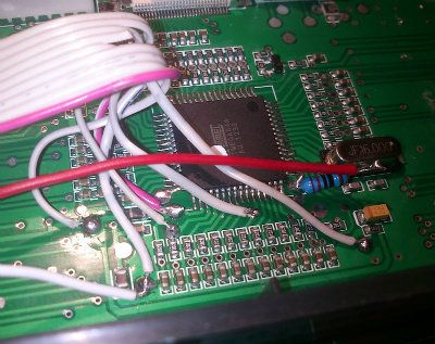
Thanks! Those current measurements seem to match mine. I'm running it directly off the pin now and it's fine. I can't imagine wanting it any brighter, I only need it in low light and it's almost too bright. Some people must install their light backwards or something if it's not very bright. I wish they had a red LED version because that is a much friendlier color for your eyes in the dark.

Looking at the specs, the ATmega64 can source 40mA absolute max on a pin and at least 200mA (or is it 400mA?) total for the chip. Since the whole radio (including TX, etc) uses less than 200mA then I think I'm more than safe. No sense adding extra bulk and complexity if it's not needed.
User avatar
MikeB
9x Developer
Posts: 17993
Joined: Tue Dec 27, 2011 1:24 pm
Country: -
Location: Poole, Dorset, UK

Re: hk backlight mod

Post by MikeB »

Note:
4] The sum of all IOL, for ports B0 - B7, G3 - G4, E0 - E7 should not exceed 100 mA.
4] The sum of all IOH, for ports B0 - B7, G3 - G4, E0 - E7 should not exceed 100 mA.

Over time the backlight units appear to use 'better' LEDs that need less current for the same brightness. Some older units needed much more current, hence the transistor drive needed.

Mike.
erskyTx/er9x developer
The difficult we do immediately,
The impossible takes a little longer!
User avatar
algo
Posts: 117
Joined: Sun Sep 02, 2012 3:11 pm
Country: -

Re: hk backlight mod

Post by algo »

MikeB wrote:Note:
4] The sum of all IOL, for ports B0 - B7, G3 - G4, E0 - E7 should not exceed 100 mA.
4] The sum of all IOH, for ports B0 - B7, G3 - G4, E0 - E7 should not exceed 100 mA.

Over time the backlight units appear to use 'better' LEDs that need less current for the same brightness. Some older units needed much more current, hence the transistor drive needed.
Thanks, do you think the radio in stock form is getting close to those limits? I don't know what it's having to drive inside there.

In any case I'd hate to think it was 5mA from burning up. :)
User avatar
MikeB
9x Developer
Posts: 17993
Joined: Tue Dec 27, 2011 1:24 pm
Country: -
Location: Poole, Dorset, UK

Re: hk backlight mod

Post by MikeB »

No, I don't think we are near those limits, just thought you should know the information. A useful test would be to measure the current draw of the 9x without the Tx module fitted.

Mike.
erskyTx/er9x developer
The difficult we do immediately,
The impossible takes a little longer!
User avatar
Scott Page
Posts: 864
Joined: Wed Dec 28, 2011 3:32 am
Country: United States
Location: Tri-Cities, Washington State

Re: hk backlight mod

Post by Scott Page »

I removed the white backing on one of these lights and put aluminum foil tape on the foam backing so it reflects better --- and it reflects much better -- no hot spots.
slimtom
Posts: 15
Joined: Fri Oct 19, 2012 2:48 am
Country: -

Re: hk backlight mod

Post by slimtom »

I would like to make a Low Voltage Drop regulator mod. I haven't foind any info so I try to do it mayslef. I'll replace stock 5V regulators with LowVoltageDrop one because I use 2S LiIon battery and this way I'll get more use of it, since the voltage can be lover and TX will stil operate than with stock 5V regulator.

I have IC L4940V5 TO220 that have like 200mV drop at 200mA current draw. Stock 5V regulator (7805) operates from 7.5 volts to 20 volts to produce 5 volts. So my batterry can be as low as 5.2V and TX would stil operate. But - anyway - LiIon must never go bellow 6V so this I am safe.

There are three 5V regulators in the 9x TX: 1 on mainboard, 1 on switchboard and one in RF module. I'll would like to replace mainboard and switchboard one's together with one new LowvoltageDrop regulator and the one in RF module. I could replace all lthree with only one LVD, but I will be using other RF modules too and some need direct batterry voltage to operate.

I would like to use existing connections in the TX to replace voltage regulator on the mainboard, BUT there is a problem. I did Backlit with transistor Mod and this mod requires to cut original connection from resistor to pin 5 and to cennect it to pin 3 (of the backlit connector). I would like to connect as drawn, but in this case resistor MUSt be connected to pin 5.

Why is there a need to cut pin5 connection and use connection to pin 3 in the backlit mod ?
LowVoltageDropRegulator.jpg
villamany
Posts: 1
Joined: Mon Dec 10, 2012 9:16 pm
Country: -

Re: hk backlight mod

Post by villamany »

Hi all, I am villamany, this is my first post. Thanks for the forum, it is very helpfull for a newbie like me ...

I've added backlight to my turnigy, I moded a old backlit panel from a graphic LCD and cutting it to dimensions of the Turnigy LCD.
The panel is illuminated by four white LEDs connected in parallel, I have not used any transistor, goes directly to the ATmega pin 17 through a 220 ohm resistor thus limiting the current (I read that Atmega can supply 20mA for output pins without problems). It is working perfect.
Is there any problem to do it by this way?

Image

Image

Post Reply

Return to “Electronic Mods”