Page 4 of 8
Re: My 9Xtreme Installation
Posted: Tue Feb 16, 2016 3:05 pm
by mmilan
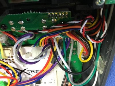
Here are the close ups of the 9 pin connectors. All wires have appropriate voltages. ( That is if the 8 "ext" pins are pulled high, as they have 5v)
Re: My 9Xtreme Installation
Posted: Tue Feb 16, 2016 3:27 pm
by bob195558
Hi mmilan,
Your first pic on the right side looks like you have in the 9 pin connector, pin 1 to be a gray wire,
but it should be your Green wire as it is connected to your Taranis Slider Brown wire +5V.
Then your pin 2 should be your White wire which is your Taranis Slider Yellow wire. (Not the Purple wire as it is now)
Then your pin 4 should be your Gray wire which is your Taranis Slider Red Ground wire.
Bob B.
Re: My 9Xtreme Installation
Posted: Tue Feb 16, 2016 3:39 pm
by mmilan
So, on the right the green wire is ground and is the gray wire 5v? The gray (pin one on both sides)is presently going to the sliders red wire and the green (pin 4) to the brown. The middle pin of the slider (signal) is going to the the yellow wire on the right (pin6 = ext2). The left signal pin is going to the white (left pin7 = ext3). Should I get 5v from something other than Pin one (gray on each side)? This sounds confusing. That's why Joao wanted pictures.
Thanks Bob
Mike
This is a 9x and pin one of the 9 pin connected is gray. This is an after market connector, so the colors are different. I just have to count from pin one each time starting with gray.
Re: My 9Xtreme Installation
Posted: Tue Feb 16, 2016 3:56 pm
by mmilan
These 9 Pin connector wires are:
Gray = Pin one 5v?
Purple = Pin 2
Blue = Pin 3
Green = Pin 4 (Ground)
Orange = Pin 5
Yellow = Pin 6
White = Pin 7
Red = Pin 8 (digital ground)
Black = Pin 9
These pictures are from the top of the Tx so Pin one is to our left in the pictures.
Re: My 9Xtreme Installation
Posted: Tue Feb 16, 2016 4:00 pm
by MikeB
Currently I have the settings for both extra pots and extra switches with the names EXT1, EXT2 etc.
I appreciate there will be some confusion as EXT1 for a switch upgrade is a different connection to EXT1 for a pot upgrade.
As a suggestion what about using SXT1, SXT2 etc. for the switch connections and PXT1, PXT2 etc. for the pot connections?
Mike.
Re: My 9Xtreme Installation
Posted: Tue Feb 16, 2016 4:01 pm
by jhsa
mmilan wrote: The middle pin of the slider (signal) is going to the the yellow wire on the right (pin6 = ext2). The left signal pin is going to the white (left pin7 = ext3).
This is your mistake.. You are connecting to the switches EXT2 and 3. Look at my picture some posts above. You need the middle wire connected to either pin 2 or 3 of the 9 pin connectors. Not 6 or 7..
Mike, this is why I suggested a while ago to change the names of the analog pins to something else.. Currently you cal EXTx to both analog and digital pins in the hardware menu, and as you can see it is really confusing..
João
Re: My 9Xtreme Installation
Posted: Tue Feb 16, 2016 4:03 pm
by jhsa
You replied at the same time as me

SXTx should be OK.. Anything that is different is ok

They are analog pins so , ANAx ANGx ALGx, etc, etc.. Any would do..
João
Re: My 9Xtreme Installation
Posted: Tue Feb 16, 2016 4:06 pm
by mmilan
So for now let's just address the left side of the Tx.
These 9 Pin connector wires are:
Gray = Pin one 5v?
Purple = Pin 2
Blue = Pin 3
Green = Pin 4 (Ground)
Orange = Pin 5 = Ext 7
Yellow = Pin 6 = Ext 8
White = Pin 7 = Ext 3
Red = Pin 8 (digital ground)
Black = Pin 9 = Ext 4
I think this is correct. Maybe I am in error getting the 5v for one side of the slider from left Pin one (Gray).
Re: My 9Xtreme Installation
Posted: Tue Feb 16, 2016 4:08 pm
by bob195558
The right side 9 pin connector counts from the Right side to Left side: 9,8,7,6,5,4,3,2,1.
I suggest you pull your right side 9 pin connector out and by lifting the small plastic catch tab (I use a sewing pin), remove wires 1,2 and 4.
Then place your Green wire in pin 1 position.
Then place your White wire in pin 2 position.
Then place your Gray wire in pin 4 position.
- from the Right side to Left side: 9,8,7,6,5,4,3,2,1
- 9 pin right side connector.jpeg (70.75 KiB) Viewed 19917 times
You need to pull your White wire that is at pin # 7 too, and move it to pin 2.
Your purple wire is not used at this time.
Bob B.
Re: My 9Xtreme Installation
Posted: Tue Feb 16, 2016 4:14 pm
by mmilan
Thanks Joao. I tried that at first. I probably misunderstood the wires. I will try again with that setup. In the hardware menu I only see choices for Pot4 (or Pot5) of Ext1 thru 4. What should I choose?
Re: My 9Xtreme Installation
Posted: Tue Feb 16, 2016 4:22 pm
by mmilan
Thanks to Bob also. I will be off to my barn(really a man cave) to rewire and let you know what happens. I am glad that it is probably a misunderstanding on my part. Joao you are correct that the labeling is confusing. In the Hardware menu the choices for Pot4 also confused me. That's why I used the switch ext_ pins for the middle wire from the slider. Sorry, ask my wife, I am often confused.
Re: My 9Xtreme Installation
Posted: Tue Feb 16, 2016 4:22 pm
by jhsa
Well, I don't know exactly which pin is what because as I said the names are confusing. But that is not difficult. First set P5 to none and keep changing the settings to P4 until you find the one that works. Then go to P5 and do the same. Of course you can't use the one that is connected to P4

This is valid as long as you connected the wires correctly of course..
João
Re: My 9Xtreme Installation
Posted: Tue Feb 16, 2016 4:50 pm
by bob195558
Hi João,
I not understanding how to make the 9Xtreme Hardware menu setting changes when following your example
of connecting the Taranis Slider (right side) to the 9 pin connector plug when using pins 1, 2 and 4.
Do we use POT 4 and/or POT 5 for the Taranis Slider pots and set them to one of the EXT #s 1 - 4 ?
Is there a chart that show what these setting are connected to ?

Bob B.
Re: My 9Xtreme Installation
Posted: Tue Feb 16, 2016 5:28 pm
by jhsa
Please read the text on the picture attached.. it is the 3rd time I attach this picture by the way. People don't seem to like to read
It's not complicated really. from the picture. It says:
Pinout of the 9 pin connectors:
Pin 1 - +5V
Pin2 - Left Vertical stick
Pin3 - Left horizontal stick
Pin4 - Analog ground.
Pins 5,6,7,9 - Trim switches (EXT inputs for extra switches)
Pin8 - Digital ground.
And then all the pins are marked and numbered on the picture.. I don't understand what is difficult, sorry. maybe I'm missing something?
Do we use POT 4 and/or POT 5 for the Taranis Slider pots and set them to one of the EXT #s 1 - 4 ?
Yes, there is no other possibility as far as I know except replacing the existing pots..
Is there a chart that show what these setting are connected to ?
Not yet.. I was hoping since the beginning that Mike would change the names.. Making a chart with the same names as the extra switches would make things even more confusing. That is why I decided to just explain how I connected my slider, and which pins I've used..
João
Re: My 9Xtreme Installation
Posted: Tue Feb 16, 2016 6:24 pm
by mmilan
Joao and Bob, thanks again for your help! I finally have Pot4 and Pot5 (Taranis sliders) working. Joao you are right about the labeling. I became confused about both the extra switches and the extra pots being connected to pins named the same: Ext1, Ext2, Ext3, and Ext4. Joao, I can read! I probably read your how to posts a dozen times. It is the menu choices that you never made clear since they are the same as the choices for the first 4 pot choices. Perhaps the pin labels and choices for the pots be changed in the Hardware menu.
Re: My 9Xtreme Installation
Posted: Tue Feb 16, 2016 6:26 pm
by MikeB
Since there are a few diagrams already posted that refer to EXT1 - EXT8, I think I shall leave these names as they are.
The 4 analog inputs I'll rename, I think to AIP1 - AIP4, meaning Analog InPut.
Mike.
Re: My 9Xtreme Installation
Posted: Tue Feb 16, 2016 6:42 pm
by jhsa
Mike, Thank you. And I find "AIPx" an excellent name.. Better than all the other possibilities..
Eeeexcellent

Thanks
João
Re: My 9Xtreme Installation
Posted: Tue Feb 16, 2016 6:45 pm
by jhsa
mmilan wrote: Joao, I can read! I probably read your how to posts a dozen times.
I know
That was meant as a joke
I will update the first post as soon as Mike releases the test version with the new names. But first I need to have a look obviously
By the way, great that the sliders are working now..
well done
João
Re: My 9Xtreme Installation
Posted: Tue Feb 16, 2016 7:04 pm
by mmilan
Thankyou Mike for the label change. It will save the next guy that, like me, who is not so electronically sophisticated a lot of time in a confused state. Thankyou Joao for your patience!
Re: My 9Xtreme Installation
Posted: Fri Feb 26, 2016 11:35 am
by lancaster
MikeB wrote:Since there are a few diagrams already posted that refer to EXT1 - EXT8, I think I shall leave these names as they are.
The 4 analog inputs I'll rename, I think to AIP1 - AIP4, meaning Analog InPut.
Mike.
Hi Mike
I know you are really busy but I have an easy question
I am planning to fit sliders to my 9Xtreme
I have trawled through the installation threads and I think I understand the process now
Do I need to install the latest Ersky firmware to get the correct hardware option?
I can get the sliders from Hobbyking but where do I get the 9 way plugs or suitable pins from?
regards
Hans
Re: My 9Xtreme Installation
Posted: Fri Feb 26, 2016 11:46 am
by jhsa
Yes, you should update to the latest version for several reasons
I think these are the right connectors. 9 pin, 2mm.
http://www.ebay.co.uk/itm/JST-2-0mm-PH- ... xyeR9TJaXs
João
Re: My 9Xtreme Installation
Posted: Fri Feb 26, 2016 12:06 pm
by lancaster
Thanks Joa for the very rapid reply -its much appreciated!
I will try your ebay link
happy flying
regards
Hans
Re: My 9Xtreme Installation
Posted: Fri Feb 26, 2016 12:11 pm
by jhsa
I think those are the right ones.. On my installation I used the ones that I removed from the taranis's gimbals.
By the way, I don't know how good that seller is.. I just did a search on ebay.. You might want to search for the same product.. maybe you even find it cheaper.
João
Re: My 9Xtreme Installation
Posted: Fri Feb 26, 2016 12:47 pm
by lancaster
Hi Joa
Yes just doing a search now
But I think your link gives good price because its for 10 sets ( male and female) - only problem is perhaps delivery time to UK
regards
Hans
Re: My 9Xtreme Installation
Posted: Fri Feb 26, 2016 1:01 pm
by jhsa
Yeah, that is always the problem

João
Re: My 9Xtreme Installation
Posted: Fri Feb 26, 2016 1:58 pm
by MikeB
Farnell have:
http://uk.farnell.com/jst-japan-solderl ... dp/3616253, and
http://uk.farnell.com/jst-japan-solderl ... dp/1830762.
You may need a crimp tool to put the wires in though!
I'm not quite sure what their postage charges and minimum order amount is these days.
Mike.
Re: My 9Xtreme Installation
Posted: Fri Feb 26, 2016 3:36 pm
by s_mack
I would suggest the pre-crimped ones João linked to. Crimping your own can be an ordeal if you don't have the proper expensive tool to do the job. They are the correct JST PH series. Even the wire colours are the same! (That can't be a coincidence, can it?)
Re: My 9Xtreme Installation
Posted: Fri Feb 26, 2016 4:07 pm
by jhsa
s_mack wrote:Even the wire colours are the same! (That can't be a coincidence, can it?)
I haven't noticed that
João
Re: My 9Xtreme Installation
Posted: Fri Feb 26, 2016 8:05 pm
by bob195558
WARNING: When upgrading the 9x Radio, do NOT trust any of the wire values by there wire colors.
China dose NOT place any particular value to any one wire color in the 9x Radios.
You should use a Multimeter and check (verify) what each wire is being used for.
9x Radios use any wire color for any wire value.
This applies within your 9x Radio and between 9x Radios.
Bob B.
Re: My 9Xtreme Installation
Posted: Fri Feb 26, 2016 10:49 pm
by willhac
The Taranis sliders are supplied with a 5 pin connector.
If you don't need all the connections you can use it, it even allows a connection for a 3 pos switch for exemple