Page 1 of 3
9XR Pro Wiring Info Q&A
Posted: Sat Jun 14, 2014 10:25 pm
by SkyNorth
Here is the wiring diagram of the Pro.
It also shows where to connect things like a Rotary encoder, Bluetooth module , and extra switches....
Edit by MikeB: The wiring for the 6-pos switch is incorrect, see 9 posts down for the correct wiring.
This shows some common modifications that users might want to do
This is what the other side of the RF Deck Board looks like:
-Brent
Re: 9XR Pro Wiring Info Q&A
Posted: Sat Jun 14, 2014 10:36 pm
by jhsa
wow, great job there Brent.. Thank you..
João
Re: 9XR Pro Wiring Info Q&A
Posted: Sun Jun 15, 2014 6:37 am
by DeathWarmedUp
Yep, brilliant! Great job Brent.
Re: 9XR Pro Wiring Info Q&A
Posted: Sun Jun 15, 2014 12:33 pm
by krisp
Thanks Brent!
Are pins 5 and 2 in the module bay pre-wired to serial rxd/txd? From this diagram it looks like pin 5 might be but pin 2 is NC?
Re: 9XR Pro Wiring Info Q&A
Posted: Sun Jun 15, 2014 11:04 pm
by jhsa
Brent, could you please have a look at the 6 position switch on your wiring diagram? Is it a 5 position switch? then there is a pin not connected? or it is like that because there wasn't enough space to put one more resistor?
João
Re: 9XR Pro Wiring Info Q&A
Posted: Sun Jun 15, 2014 11:13 pm
by SkyNorth
krisp wrote:Thanks Brent!
Are pins 5 and 2 in the module bay pre-wired to serial rxd/txd? From this diagram it looks like pin 5 might be but pin 2 is NC?
Pin 5 is wired to COM1 bi-directional serial port. Pin 2 is open . If you want to connect COM2 for internal use , then you need to remove the Pin2 wire (COM1) and add the 2 COM2 connections as shown.
Re: 9XR Pro Wiring Info Q&A
Posted: Sun Jun 15, 2014 11:18 pm
by SkyNorth
jhsa wrote:Brent, could you please have a look at the 6 position switch on your wiring diagram? Is it a 5 position switch? then there is a pin not connected? or it is like that because there wasn't enough space to put one more resistor?
João
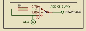
The A/D input on this pin is biased at 1/2 VCC by two 2.2K resistors. So when the the switch is connected to that position , you get a
1/2VCC input ...This is how the 3 way switch works with only 2 wires.
Re: 9XR Pro Wiring Info Q&A
Posted: Sun Jun 15, 2014 11:25 pm
by jhsa
So if I understood, if left unconnected it will be at half position, correct? because of the resistors that are already there before the 6 pos switch..
João
EDIT: I think I get it.. On the 3 position switch (with 2 wires) the 1K resistor that we solder to the switch will be paralleled with the 2.2K resistor form the divider already present on that pin.. So, then we get, pin to ground (0V), then in the middle position we get the value from the existing divider (1/2 VCC), and the switch at the top position has the combined resistance from both resistors paralleled and will give us another voltage, somewhere between half VCC and ground..

Re: 9XR Pro Wiring Info Q&A
Posted: Sun Jun 15, 2014 11:46 pm
by SkyNorth
i have the 2.2K resistor on the wrong side of the switch
It should be like this .... (I have shown the bias resistors in the drawing they are already in the circuit.
-Brent
Re: 9XR Pro Wiring Info Q&A
Posted: Sun Jun 15, 2014 11:50 pm
by jhsa
yes, this makes definitely more sense

Thanks
João
Re: 9XR Pro Wiring Info Q&A
Posted: Mon Jun 16, 2014 11:44 am
by jhsa
Tried to upload the diagram to the radio's "files" section at HK.
Guess what? It doesn't let me.. I mean uploads but never comes online.. I wonder why.

João
Re: 9XR Pro Wiring 6-Pos update
Posted: Thu Jun 19, 2014 5:15 pm
by SynergyHub
Thank you very much.
Re: 9XR Pro Wiring Info Q&A
Posted: Sat Jul 05, 2014 10:04 pm
by krisp
Trying to clarify which serial ports are which.. currently opentx uses the following for the serial ports:
USART0 for telemetry, which is defined as #define SECOND_USART USART0
UART1 for bluetooth,defined as #define BT_USART UART1
Do these map to COM2 and COM3 in the above picture?
Thanks
Re: 9XR Pro Wiring Info Q&A
Posted: Sat Jul 05, 2014 10:24 pm
by MikeB
That looks to be correct.
Mike.
Re: 9XR Pro Wiring Info Q&A
Posted: Sun Jul 06, 2014 6:55 pm
by fburden
Great new diagrams!
is this a typo? "input from doing 3/6 way mod"
should it be "input to do 3/6 way mod"?
Ford
Re: 9XR Pro Wiring Info Q&A
Posted: Sun Jul 06, 2014 7:11 pm
by jhsa
no, it is right.. this uses the ELE_DR input from doing........
The input it uses was left from doing the other one.. Now we can use the one that was left to do another one

You can not change another switch on that side without replacing the ELE switch first.
Re: 9XR Pro Wiring Info Q&A
Posted: Sun Jul 06, 2014 7:43 pm
by KAL
But this part of the diagram
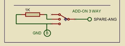
- 3pos mod for ELE-DR #2.jpg (11.01 KiB) Viewed 67614 times
should be replaced by somewhat like this
- 3pos mod for ELE-DR #3.jpg (27.24 KiB) Viewed 67610 times
because spare-ang has to be connected to the mid pin of the 3-pos switch.
The outer pins have to be connected via the resistor.
One of the outer pins has to be connected to ground.
The upper diagram (as how it's in the actual diagram '9XR_Pro_wire_1_1.JPG')
is somewhat misleading in terms of wiring the switch ...
Just my 2 cts.
Klaus
Re: 9XR Pro Wiring Info Q&A
Posted: Sun Jul 06, 2014 7:56 pm
by jhsa
you're right, it looks like it is wrong..
Hmmm, I think I understand what he did there..
Mike, will I have to change my 3 position switch connections??

It is actually easy to solder a resistor between both outer pins than the middle and outer pin..
what about all the people that already did it the other way? the old file has been posted everywhere

Why can't we just leave it as it was before? it works the same, right?
João
Re: 9XR Pro Wiring Info Q&A
Posted: Sun Jul 06, 2014 8:06 pm
by KAL
As I see it, the symbol for the switch is wrong, 'cause the switch needed
by us has only 3 pins, not 4 as in the diagram.
We need a 3-pos switch (on/off/on) with mid pos unconnected, not a 3-way switch.
Klaus
Re: 9XR Pro Wiring Info Q&A
Posted: Sun Jul 06, 2014 8:11 pm
by MikeB
Yes, keep to the 1K resistor across the outer two pins, That's what the firmware is looking for.
Mike.
Re: 9XR Pro Wiring Info Q&A
Posted: Sun Jul 06, 2014 8:23 pm
by KAL
Just like it is shown in the
Switch Upgrades thread.
Klaus
Re: 9XR Pro Wiring Info Q&A
Posted: Sun Jul 06, 2014 8:31 pm
by jhsa
Yes, but the diagrams should be changed back then..
Why changing something that was working good??
João
Re: 9XR Pro Wiring Info Q&A
Posted: Sun Jul 06, 2014 8:51 pm
by KAL
Just like this?
Klaus
Re: 9XR Pro Wiring Info Q&A
Posted: Sun Jul 06, 2014 9:22 pm
by KAL
And for the sake of completeness ...
Klaus
Re: 9XR Pro Wiring Info Q&A
Posted: Sun Jul 06, 2014 10:21 pm
by SkyNorth
drawings fixed
Re: 9XR Pro Wiring Info Q&A
Posted: Sun Jul 06, 2014 10:49 pm
by jhsa
Brent I think I understand what you meant. From an electronic point of view it might be more correct the way you did earlier. But the fact is, what we had before works because the code follows the design, and I guess some people already did it the other way. I think it is one of those things that it's not worth to change because it is working.. if we change it, it would do exactly the same thing with no gain.
João
Re: 9XR Pro Wiring Info Q&A
Posted: Sun Jul 06, 2014 11:29 pm
by SkyNorth
the change was NOT intentional
Re: 9XR Pro Wiring Info Q&A
Posted: Sun Jul 06, 2014 11:37 pm
by jhsa
Oh, ok then.. In that case we forgive you
Maybe Chippy was playing with your computer this time?
João
Re: 9XR Pro Wiring Info Q&A
Posted: Mon Jul 07, 2014 8:17 am
by MikeB
Brent: The second drawing in this post:
viewtopic.php?f=122&t=5659#p80481 is still wrong.
Mike.
Re: 9XR Pro Wiring Info Q&A
Posted: Mon Jul 07, 2014 12:50 pm
by SkyNorth
Thanks Mike , I removed the bad diagram.