FrSky Hardware / Software / RF protocol hacking
Posted: Wed Apr 11, 2012 9:35 am
Well, some insights at least...
Following the discussion in this thread, as I had nothing to do on that free Monday I did what I suggested:
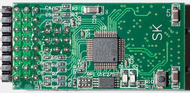
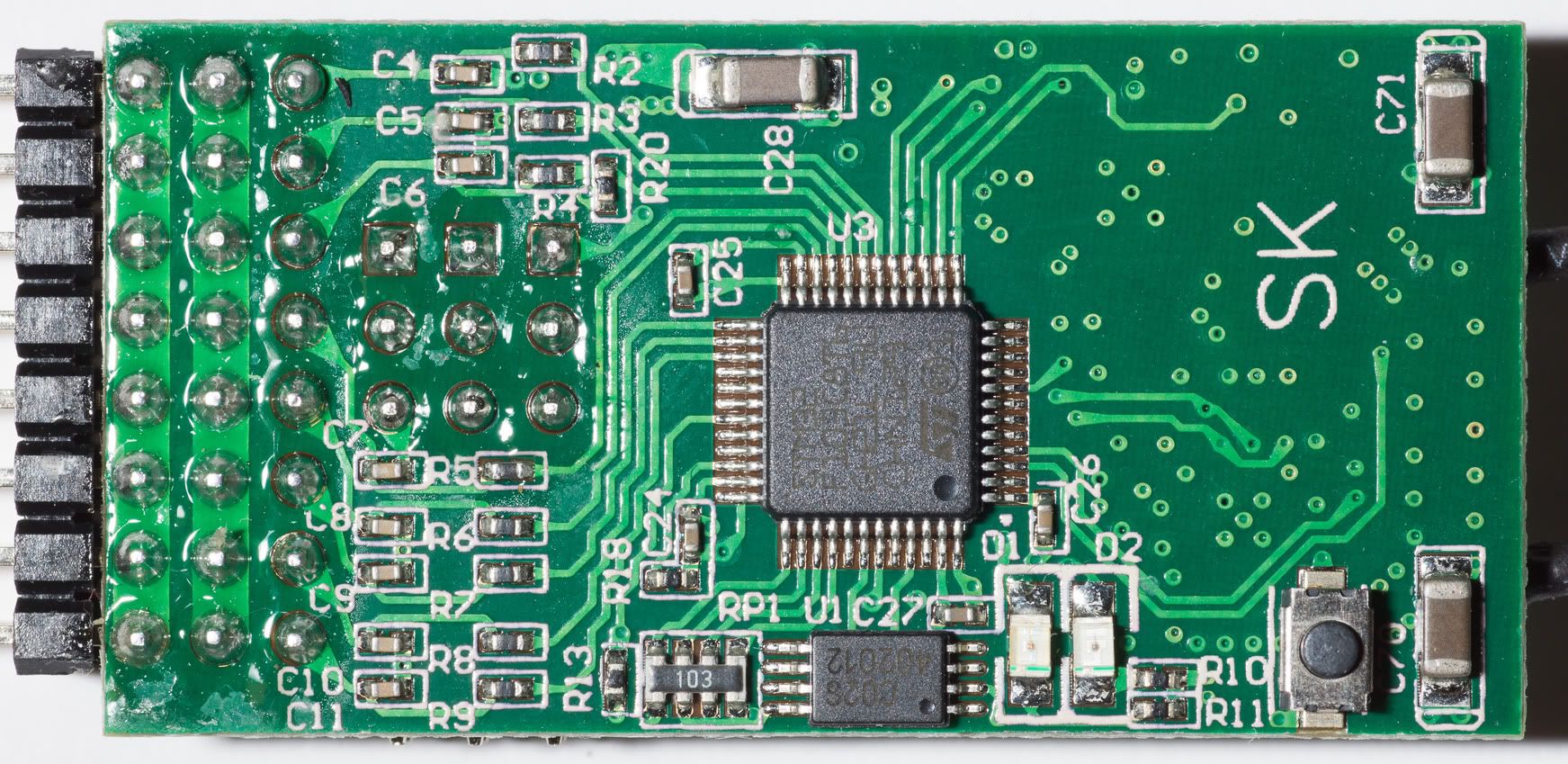
Bottom:
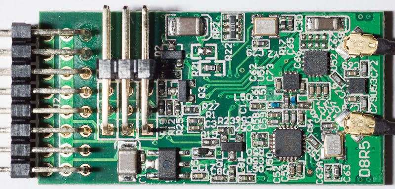
Top:
Logic analyser connections:
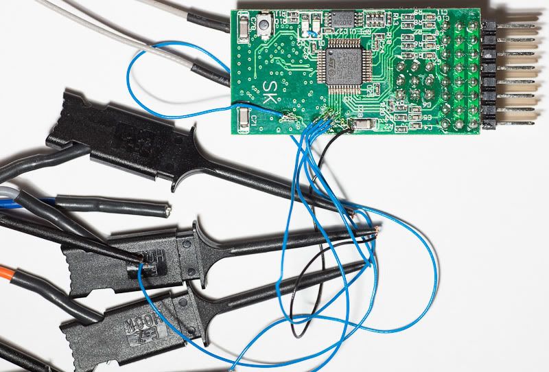
So I tapped the SPI connection between the receiver's main processor (STMicro STM103C8) and the RF chip (Texas Instruments CC2500) and went on to capture one dataset in the following conditions:
The whole thing expectedly starts by a RESET of the CC2500, then a rather large stream of register writes to initialise the chip. I've decoded about half of it, then went on to the more interesting stuff, maybe to come back later:
Format is:
Sequence number - Data - What it actually means on the registers (Description). Shouldn't be line-wrapped, but forum decides otherwise.
Not terribly interesting at this point, which is why I didn't go further yet. One thing to note is the 31kbps RF baudrate and 300kHz channel spacing. The chip apparently computes the channels itself, once configured changing channel is just an affair of writing to a 1-byte channel number register.
Following this, the actual "routine" communications start:
A lot of stuff that makes a rather simple pattern evident:
The frames look like this, FrSky were nice enough to break down the uplink buffer reads into 4 parts, hinting at particular meanings for each. That's what the breaks are. The downlink frame is in one write.
So, the conclusions I have up to now are the following:
The uplink frame consists in:
My oscillating CH1 seemed to hint at the 7th byte being the LSB, but the MSBs were somewhere in the 11th byte. CH2 seemed to affect the 2nd and 11th bytes.
The interesting thing is that apart from this detail it's a very easy transmission scheme. Wouldn't be hard to replicate
I haven't yet looked into how antenna and TX/RX switching was implemented.
Following the discussion in this thread, as I had nothing to do on that free Monday I did what I suggested:
As a starter, a couple of high res pictures of a D8RSP, identical to a D8RII (click for larger size, apparently photobucket didn't keep my 17MP files...):Kilrah wrote:Someone will have to tap a logic analyzer between the STM32 and the CC2500 at some point
Bottom:
Top:

Logic analyser connections:
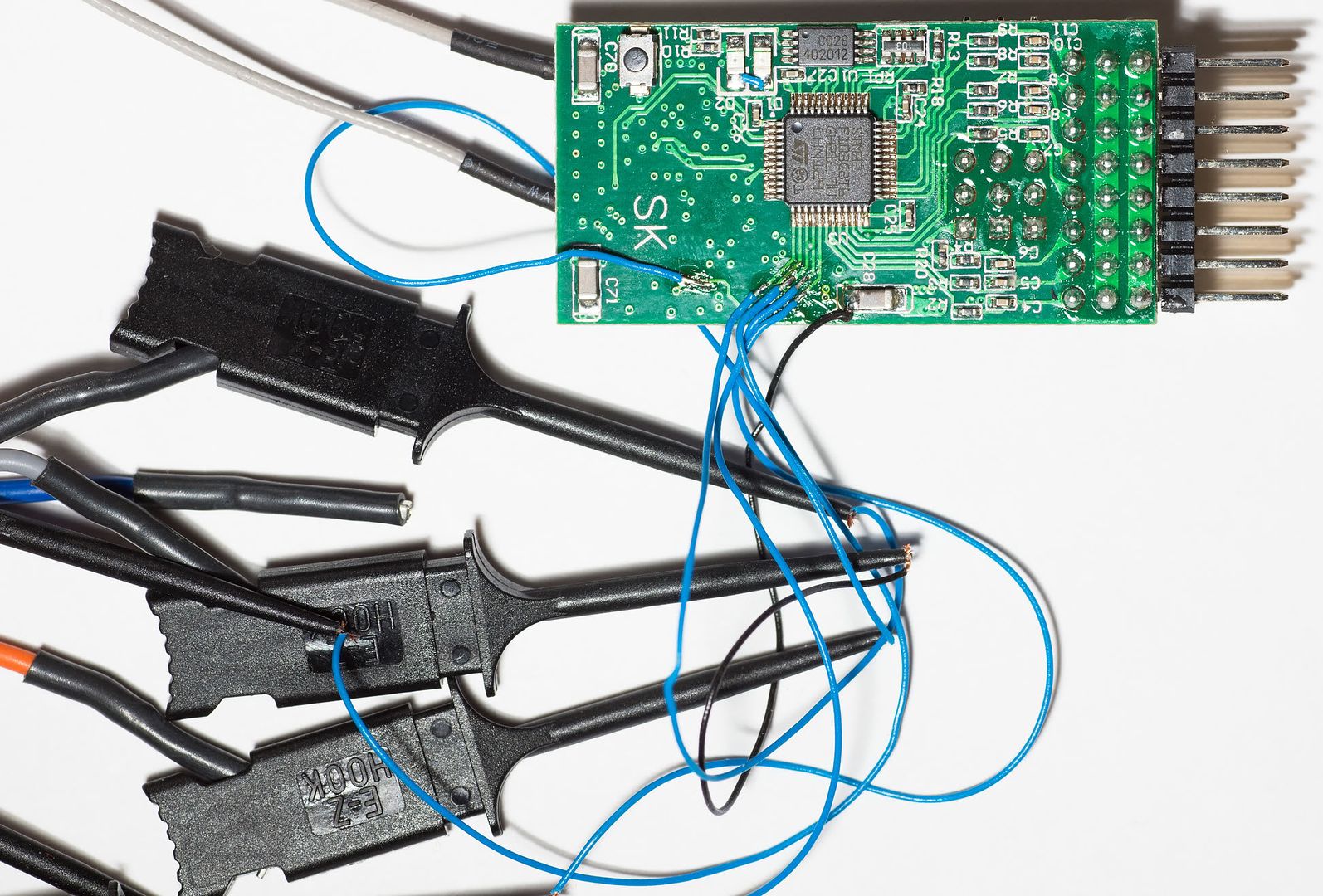
So I tapped the SPI connection between the receiver's main processor (STMicro STM103C8) and the RF chip (Texas Instruments CC2500) and went on to capture one dataset in the following conditions:
- Radio on and previously bound
- Capture from time receiver is powered up
The whole thing expectedly starts by a RESET of the CC2500, then a rather large stream of register writes to initialise the chip. I've decoded about half of it, then went on to the more interesting stuff, maybe to come back later:
Format is:
Sequence number - Data - What it actually means on the registers (Description). Shouldn't be line-wrapped, but forum decides otherwise.
Code: Select all
01 - (0x30) RESET
02 - (0x02 0x06) GDO0_INV = 0 / GDO0_CFG = 6 (Asserts when sync word has been sent / received, and de-asserts at the end of the packet. In RX, the pin will de-assert when the optional address check fails or the RX FIFO overflows. In TX the pin will de-assert if the TX FIFO underflows)
03 - (0x00 0x06) GDO2_INV = 0 / GDO2_CFG = 6 (Asserts when sync word has been sent / received, and de-asserts at the end of the packet. In RX, the pin will de-assert when the optional address check fails or the RX FIFO overflows. In TX the pin will de-assert if the TX FIFO underflows)
04 - (0x17 0x0C) CCA_MODE = 0 (Always) / RXOFF_MODE = 0x11 (Select what should happen when a packet has been received - Stay in RX) / TXOFF_MODE = 0 (Select what should happen when a packet has been sent (TX) - IDLE)
05 - (0x18 0x18) FS_AUTOCAL = 0x01 (Automatically calibrate when going from IDLE to RX or TX (or FSTXON)) / PO_TIMEOUT = 0x10 (Programs the number of times the six-bit ripple counter must expire after XOSC has stabilized before CHP_RDYn goes low. - Expire count 64 Approx. 149 – 155 µs)
06 - (0x06 0x19) PKTLEN=0x19
07 - (0x07 0x04) PQT = 0 (When PQT=0 a sync word is always accepted.) / CRC_AUTOFLUSH = 0 / APPEND_STATUS = 1 (When enabled, two status bytes will be appended to the payload of the packet. The status bytes contain RSSI and LQI values, as well as the CRC OK flag.) / ADR_CHK = 0 (No address check)
08 - (0x08 0x05) WHITE_DATA = 0 / PKT_FORMAT = 0 (Normal mode, use FIFOs for RX and TX) / CC2400_EN = 0 / CRC_EN = 1 (CRC calculation in TX and CRC check in RX enabled) / LENGTH_CONFIG = 1 (Variable packet length mode. Packet length configured by the first byte after sync word)
09 - (0x3E 0xFF) PATABLE(0) = 0xFF (+1dBm)
10 - (0x0B 0x08) FREQ_IF = 0x08 (IF = 203.125kHz)
11 - (0x0C 0x00) FREQOFF = 0
12 - (0x0D 0x5C 0x0E 0x76 0x0F 0x27) FREQ = 0x5C7627 (F = 2404MHz)
13 - (0x10 0xAA) CHANBW_E = 0x10 / CHANBW_M = 0x10 Sets the decimation ratio for the delta-sigma ADC input stream and thus the channel bandwidth. BW = 135.417kHz / DRATE_E = 0x0A
14 - (0x11 0x39) DRATE_M = 0x39 Bitrate = 31044 bps
15 - (0x12 0x11) MOD_FORMAT = 0x01 (GFSK) / SYNC_MODE = 0x01 (15/16 sync word bits detected)
16 - (0x13 0x23) FEC_EN = Disable / NUM_PREAMBLE = 0x02 (4 bytes) / CHANSPC_E = 0x03
17 - (0x14 0x7A) CHANSPC_M = 0x7A Channel Spacing = 299927Hz
18 - (0x15 0x42) DEVIATION_E = 0x100 / DEVIATION_M = 0x02 Deviation mantissa, interpreted as a 4-bit value with MSB implicit 1. Deviation = 31738Hz
19 - (0x19 0x16) FOC_BS_CS_GATE = 0 / FOC_PRE_K = 0x10 (The frequency compensation loop gain to be used before a sync word is detected. - 3K) / FOC_POST_K = 1 (The frequency compensation loop gain to be used after a sync word is detected. - K/2) / FOC_LIMIT = 0x10 (The saturation point for the frequency offset compensation algorithm - ±BWCHAN/4)
20 - (0x1A 0x6C) BS_PRE_KI = 0x01 (2KI) / BS_PRE_KP = 0x10 (3KP) / BS_POST_KI = 1 (KI /2) / BS_POST_KP = 1 (Kp) / BS_LIMIT = 0 (No data rate offset compensation performed)
21 - (0x1B 0x03) MAX_DVGA_GAIN = 0 (All gain settings can be used) / MAX_LNA_GAIN = 0 (Maximum possible LNA + LNA 2 gain) / MAGN_TARGET = 0x011 (Target amplitude from channel filter = 33dB)
... not finished decoding initialisationFollowing this, the actual "routine" communications start:
Code: Select all
First channel set
(0x36) SIDLE Exit RX / TX, turn off frequency synthesizer and exit Wake-On-Radio mode if applicable.
(0x0A 0x53) CHANNR = 0x53
(0x23 0x89) Set Frequency Synthesizer Calibration Parameters
[1.39ms]
(0x34) SRX Enable RX. Perform calibration first if coming from IDLE and MCSM0.FS_AUTOCAL=1.

[100ms]

(0xFB) RXBYTES Overflow and number of bytes in the RX FIFO (0x14)
(0xDB)
(0xFB) RXBYTES Overflow and number of bytes in the RX FIFO (0x14)
(0xDB)
(0xFF) Burst access to RX FIFO - 1 byte (0x11)
(0xFF) Burst access to RX FIFO - 2 bytes (0x85 0x2D)
(0xFF) Burst access to RX FIFO - 15 bytes (0x8E 0x00 0x01 0x38 0xF9 0xCB 0x54 0x89 0x85 0xCB 0xCB 0xCB 0xCB 0x88 0x55)
(0xFF) Burst access to RX FIFO - 2 bytes (0x72 0xB1)

[0.5ms]

(0x36) SIDLE Exit RX / TX, turn off frequency synthesizer and exit Wake-On-Radio mode if applicable.
(0x0A 0xA3) CHANNR = 0xA3
(0x23 0x89) Set Frequency Synthesizer Calibration Parameters

[1.37ms]

(0x3A) SFRX Flush the RX FIFO buffer. Only issue SFRX in IDLE or RXFIFO_OVERFLOW states.
(0x3B) SFTX Flush the TX FIFO buffer. Only issue SFTX in IDLE or TXFIFO_UNDERFLOW states.
(0x7F) Burst access to TX FIFO - 18 bytes (0x11 0x85 0x2D 0x7B 0x85 0x0F 0x00 0x00 0x00 0x00 0x00 0x00 0x00 0x00 0x00 0x00 0x00 0x00)
(0x35) 0x35 STX In IDLE state: Enable TX. Perform calibration first if MCSM0.FS_AUTOCAL=1. If in RX state and CCA is enabled: Only go to TX if channel is clear.

[7.47ms]

(0x36) SIDLE Exit RX / TX, turn off frequency synthesizer and exit Wake-On-Radio mode if applicable.
(0x0A 0x08) CHANNR = 0x08
(0x23 0x89) Set Frequency Synthesizer Calibration Parameters

[1.39ms]

(0x34) SRX Enable RX. Perform calibration first if coming from IDLE and MCSM0.FS_AUTOCAL=1.
(0xFB) RXBYTES Overflow and number of bytes in the RX FIFO (0x14)
(0xDB)
(0xFB) RXBYTES Overflow and number of bytes in the RX FIFO (0x14)
(0xDB)
(0xFF) Burst access to RX FIFO - 1 byte (0x11)
(0xFF) Burst access to RX FIFO - 2 bytes (0x85 0x2D)
(0xFF) Burst access to RX FIFO - 15 bytes (0x90 0x00 0x01 0x38 0xF9 0xCB 0x54 0x89 0x85 0xCB 0xCB 0xCB 0xCB 0x88 0x55)
(0xFF) Burst access to RX FIFO - 2 bytes (0x72 0xB1)

[0.5ms]

(0x36) SIDLE Exit RX / TX, turn off frequency synthesizer and exit Wake-On-Radio mode if applicable.
(0x0A 0x58) CHANNR = 0x58
(0x23 0x89) Set Frequency Synthesizer Calibration Parameters

[1.39ms]

(0x34) SRX Enable RX. Perform calibration first if coming from IDLE and MCSM0.FS_AUTOCAL=1.

[6.93ms]

(0xFB) RXBYTES Overflow and number of bytes in the RX FIFO (0x14)
(0xDB)
(0xFB) RXBYTES Overflow and number of bytes in the RX FIFO (0x14)
(0xDB)
(0xFF) Burst access to RX FIFO - 1 byte (0x11)
(0xFF) Burst access to RX FIFO - 2 bytes (0x85 0x2D)
(0xFF) Burst access to RX FIFO - 15 bytes (0x91 0x00 0x01 0x38 0xF9 0xCB 0x54 0x89 0x85 0xCB 0xCB 0xCB 0xCB 0x88 0x55)
(0xFF) Burst access to RX FIFO - 2 bytes (0x72 0xB1)

[0.5ms]

(0x36) SIDLE Exit RX / TX, turn off frequency synthesizer and exit Wake-On-Radio mode if applicable.
(0x0A 0xA8) CHANNR = 0xA8
(0x23 0x89) Set Frequency Synthesizer Calibration Parameters

[1.39ms]

(0x34) SRX Enable RX. Perform calibration first if coming from IDLE and MCSM0.FS_AUTOCAL=1.

[6.93ms]

(0xFB) RXBYTES Overflow and number of bytes in the RX FIFO (0x14)
(0xDB)
(0xFB) RXBYTES Overflow and number of bytes in the RX FIFO (0x14)
(0xDB)
(0xFF) Burst access to RX FIFO - 1 byte (0x11)
(0xFF) Burst access to RX FIFO - 2 bytes (0x85 0x2D)
(0xFF) Burst access to RX FIFO - 15 bytes (0x92 0x00 0x01 0x38 0xF9 0xCB 0x55 0x89 0x85 0xCB 0xCB 0xCB 0xCB 0x88 0x55)
(0xFF) Burst access to RX FIFO - 2 bytes (0x6D 0xB1)

[0.5ms]


(0x36) SIDLE Exit RX / TX, turn off frequency synthesizer and exit Wake-On-Radio mode if applicable.
(0x0A 0x0D) CHANNR = 0x0D
(0x23 0x89) Set Frequency Synthesizer Calibration Parameters

[1.37ms]

(0x3A) SFRX Flush the RX FIFO buffer. Only issue SFRX in IDLE or RXFIFO_OVERFLOW states.
(0x3B) SFTX Flush the TX FIFO buffer. Only issue SFTX in IDLE or TXFIFO_UNDERFLOW states.
(0x7F) Burst access to TX FIFO - 18 bytes (0x11 0x85 0x2D 0x7E 0x86 0x3C 0x00 0x00 0x00 0x00 0x00 0x00 0x00 0x00 0x00 0x00 0x00 0x00)
(0x35) 0x35 STX In IDLE state: Enable TX. Perform calibration first if MCSM0.FS_AUTOCAL=1. If in RX state and CCA is enabled: Only go to TX if channel is clear.

[7.47ms]

(0x36) SIDLE Exit RX / TX, turn off frequency synthesizer and exit Wake-On-Radio mode if applicable.
(0x0A 0x5D) CHANNR = 0x5D
(0x23 0x89) Set Frequency Synthesizer Calibration Parameters

[1.39ms]

(0x34) SRX Enable RX. Perform calibration first if coming from IDLE and MCSM0.FS_AUTOCAL=1.

[6.93ms]

(0xFB) RXBYTES Overflow and number of bytes in the RX FIFO (0x14)
(0xDB)
(0xFB) RXBYTES Overflow and number of bytes in the RX FIFO (0x14)
(0xDB)
(0xFF) Burst access to RX FIFO - 1 byte (0x11)
(0xFF) Burst access to RX FIFO - 2 bytes (0x85 0x2D)
(0xFF) Burst access to RX FIFO - 15 bytes (0x94 0x00 0x01 0x38 0xF9 0xCB 0x55 0x89 0x85 0xCB 0xCB 0xCB 0xCB 0x88 0x55)
(0xFF) Burst access to RX FIFO - 2 bytes (0x73 0xB0)

etc
- The RF frame period is 9ms
- Channel hops every frame
- Every 4th frame is a downlink frame. So we get 3 uplink frames, one downlink, and repeat
- Packet size is constant, an uplink frame always contains 20 bytes, a downlink frame always contains 18 bytes
The frames look like this, FrSky were nice enough to break down the uplink buffer reads into 4 parts, hinting at particular meanings for each. That's what the breaks are. The downlink frame is in one write.
Code: Select all
CH1 oscillating

11 	85 2D 	64 08 01 8E CB CB CB 88 88 CB CB CB CB 88 88 	5D AF
11 	85 2D 	65 08 01 BC CB CB CB 88 88 CB CB CB CB 88 88	5B AF
11 	85 2D	66 08 01 BC CB CB CB 88 88 CB CB CB CB 88 88	5D B0

11 85 2D 60 77 5F 00 00 00 00 00 00 00 00 00 00 00 00

11 	85 2D 	68 08 01 DA CB CB CB 88 88 CB CB CB CB 88 88	5E AD
11 	85 2D	69 08 01 DA CB CB CB 88 88 CB CB CB CB 88 88	19 AC
11 	85 2D	6A 08 01 F9 CB CB CB 88 88 CB CB CB CB 88 88	27 B0

11 85 2D 60 77 66 00 00 00 00 00 00 00 00 00 00 00 00

11 	85 2D	6C 08 01 17 CB CB CB 89 88 CB CB CB CB 88 88	1B AE
11 	85 2D	6D 08 01 17 CB CB CB 89 88 CB CB CB CB 88 88	28 AF
11 	85 2D	6E 08 01 17 CB CB CB 89 88 CB CB CB CB 88 88	29 B0

11 85 2D 60 77 5C 00 00 00 00 00 00 00 00 00 00 00 00

11 	85 2D	70 08 01 45 CB CB CB 89 88 CB CB CB CB 88 88	1B AF
11 	85 2D	71 08 01 64 CB CB CB 89 88 CB CB CB CB 88 88	2A B0
11 	85 2D	72 08 01 64 CB CB CB 89 88 CB CB CB CB 88 88	29 AE

11 85 2D 5F 76 51 00 00 00 00 00 00 00 00 00 00 00 00

11 	85 2D	74 08 01 83 CB CB CB 89 88 CB CB CB CB 88 88	1E B1
11 	85 2D	75 08 01 83 CB CB CB 89 88 CB CB CB CB 88 88	29 B0
11 	85 2D	76 08 01 A1 CB CB CB 89 88 CB CB CB CB 88 88	28 AF

11 85 2D 60 77 52 00 00 00 00 00 00 00 00 00 00 00 00

11 	85 2D	78 08 01 A1 CB CB CB 89 88 CB CB CB CB 88 88	1B B0
11 	85 2D	79 08 01 D0 CB CB CB 89 88 CB CB CB CB 88 88	29 B1
11 	85 2D	7A 08 01 D0 CB CB CB 89 88 CB CB CB CB 88 88	2C AE

11 85 2D 60 77 53 00 00 00 00 00 00 00 00 00 00 00 00

11 	85 2D	7C 08 01 EF CB CB CB 89 88 CB CB CB CB 88 88	20 AF
11 	85 2D	7D 08 01 EF CB CB CB 89 88 CB CB CB CB 88 88	2E AF
11 	85 2D	7E 08 01 0D CB CB CB 8A 88 CB CB CB CB 88 88	2A B0

11 85 2D 60 77 53 00 00 00 00 00 00 00 00 00 00 00 00The uplink frame consists in:
- 0x11, fixed header
- A 2-byte TX identifier. This one will change when bound to another TX
- A 1-byte frame counter. It includes downlink frames even if not transmitted in them
- 14 bytes of channel data. Haven't managed to crack down the arrangement yet, but it looks messy. It's so not straightforward that I wouldn't be surprised if there's some encoding going on
- 2 bytes which are most likely a checksum
- 0x11, fixed header
- The same 2-byte TX identifier
- 1 byte for A0 (plain ADC value)
- 1 byte for A1 (plain ADC value)
- 1 byte for RSSI (plain value too)
- 12 bytes of user data if any, they're transmitted as 0x00 if nothing's connected
My oscillating CH1 seemed to hint at the 7th byte being the LSB, but the MSBs were somewhere in the 11th byte. CH2 seemed to affect the 2nd and 11th bytes.
The interesting thing is that apart from this detail it's a very easy transmission scheme. Wouldn't be hard to replicate
I haven't yet looked into how antenna and TX/RX switching was implemented.