its my first post here, because i cant find any Information at other forums.
Does anyone know, how to install the Corona CT14F , 14 Channel Transmitter into the 9X ?
I know, that is not fitting into the Transmitter Slot of the 9X, but i have an old one, that i can use.
I flashed my 9X with the ER9X Firmware.
Which settings must i adjust to have 14 Channels?
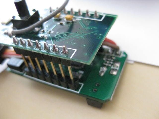
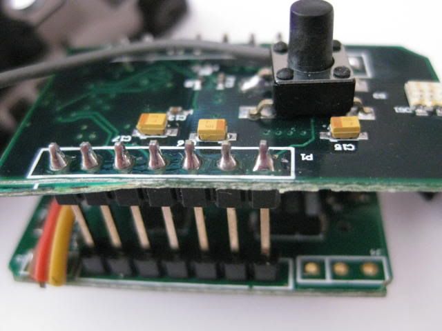
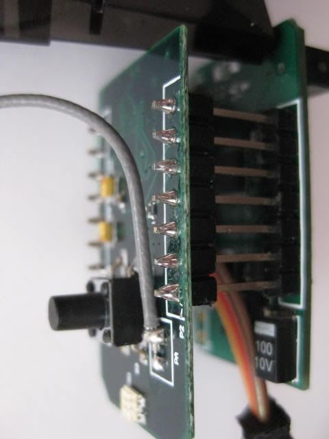
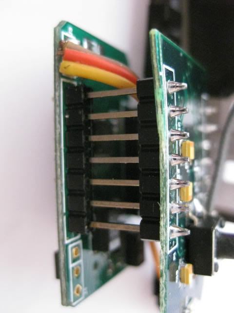
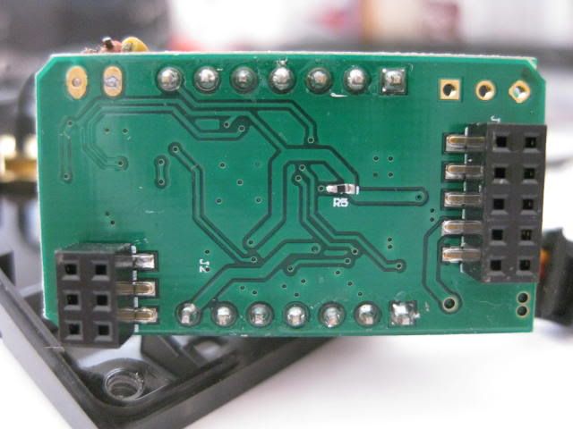
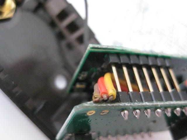
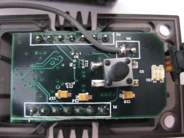
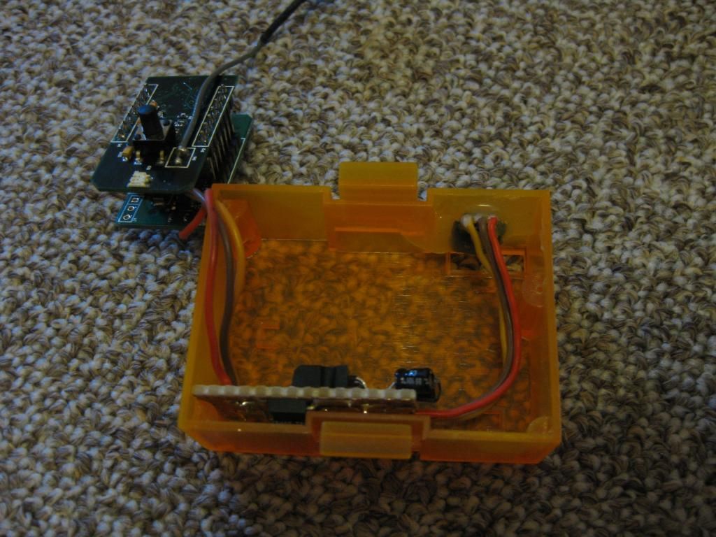
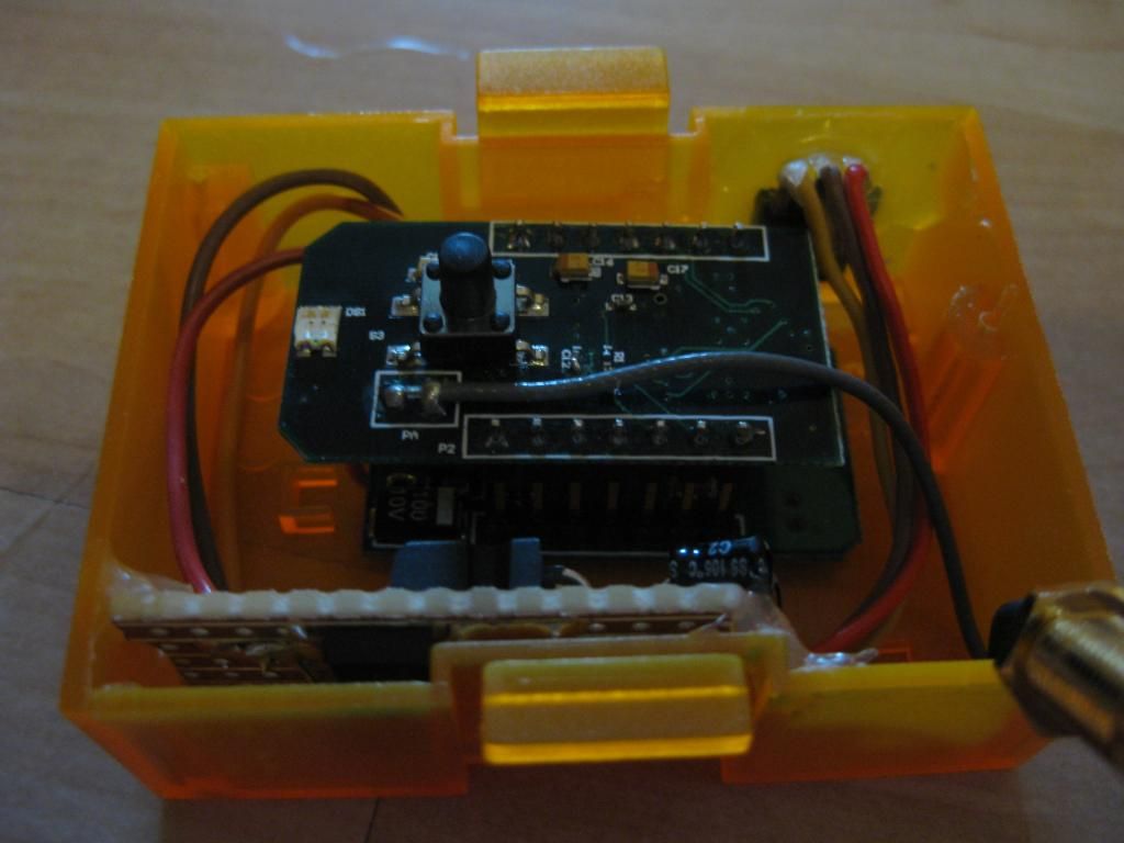
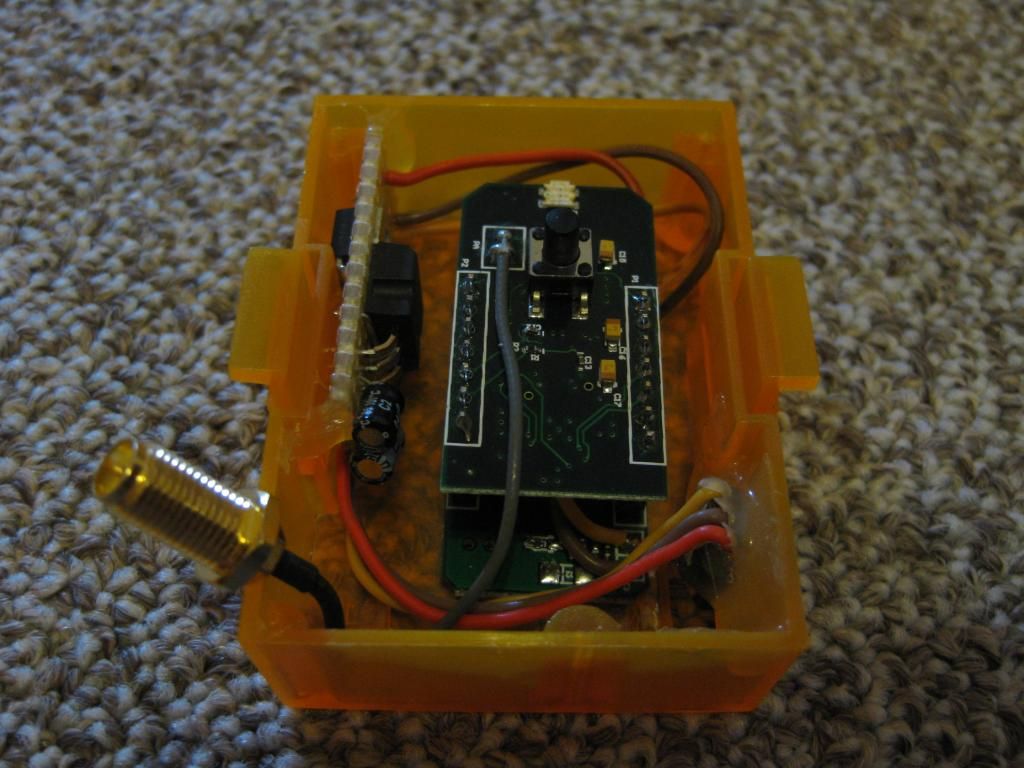
Thats the module i want to install:
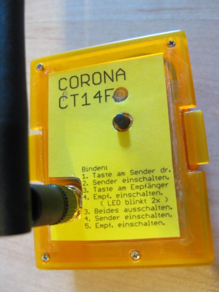
Corona 14 Channel Modul

Thanks a lot for your help.