Orange Module running MULTI protocol
-
Raptor4167
- Posts: 25
- Joined: Wed Mar 29, 2017 7:31 pm
- Country: -
-
Raptor4167
- Posts: 25
- Joined: Wed Mar 29, 2017 7:31 pm
- Country: -
Re: Orange Module running MULTI protocol
I'm also using the module bay as the power source
-
MikeB

- 9x Developer
- Posts: 17992
- Joined: Tue Dec 27, 2011 1:24 pm
- Country: -
- Location: Poole, Dorset, UK
Re: Orange Module running MULTI protocol
Please double check you have the clock and data signals correct, the TMSCLK signal is the DATA.
Mike.
Mike.
erskyTx/er9x developer
The difficult we do immediately,
The impossible takes a little longer!
The difficult we do immediately,
The impossible takes a little longer!
-
Raptor4167
- Posts: 25
- Joined: Wed Mar 29, 2017 7:31 pm
- Country: -
Re: Orange Module running MULTI protocol
does the code 1E95 4201 00BF FEFF 00FF mean that it worked. I don't have a way of testing it since I broke the attenna wire off right at the attenna connector
-
MikeB
- 9x Developer
- Posts: 17992
- Joined: Tue Dec 27, 2011 1:24 pm
- Country: -
- Location: Poole, Dorset, UK
Re: Orange Module running MULTI protocol
1E9542 is correct for the signature, so that read OK, which means as long as the flashing completed without showing "FAILED", then it most likely worked.
Mike.
Mike.
erskyTx/er9x developer
The difficult we do immediately,
The impossible takes a little longer!
The difficult we do immediately,
The impossible takes a little longer!

Re: Orange Module running MULTI protocol
Hi Mike,
I tried to program a Blue module of a friend. Bu I got this error message:
I don't know what is wrong.
The connection seems to be fine, since at the beginning the device signature is correct.
Any help will be very much appreciate.
Seb
I tried to program a Blue module of a friend. Bu I got this error message:
Code: Select all
MultiOrange.hex: 16 234 / 36 864 Bytes (44,04%)
~ ~ ~ ~ ~ ~ ~ ~ ~ ~ ~ ~ ~ ~ ~ ~

avrdude.exe: Version 6.3, compiled on Dec 16 2016 at 13:33:19
             Copyright (c) 2000-2005 Brian Dean, http://www.bdmicro.com/
             Copyright (c) 2007-2014 Joerg Wunsch

             System wide configuration file is "C:\Users\scharpen\Documents\github\AVRDUDESS\avrdude.conf"

             Using Port                    : usb
             Using Programmer              : avrispmkII
avrdude.exe: usbdev_open(): Found AVRISP mkII, serno: 000200212345
             AVR Part                      : ATxmega32D4
             Chip Erase delay              : 0 us
             PAGEL                         : P00
             BS2                           : P00
             RESET disposition             : dedicated
             RETRY pulse                   : SCK
             serial program mode           : yes
             parallel program mode         : yes
             Timeout                       : 0
             StabDelay                     : 0
             CmdexeDelay                   : 0
             SyncLoops                     : 0
             ByteDelay                     : 0
             PollIndex                     : 0
             PollValue                     : 0x00
             Memory Detail                 :

                                      Block Poll               Page                       Polled
               Memory Type Mode Delay Size  Indx Paged  Size   Size #Pages MinW  MaxW   ReadBack
               ----------- ---- ----- ----- ---- ------ ------ ---- ------ ----- ----- ---------
               signature      0     0     0    0 no          3    0      0     0     0 0x00 0x00
               prodsig        0     0     0    0 no         50   50      0     0     0 0x00 0x00
               fuse1          0     0     0    0 no          1    0      0     0     0 0x00 0x00
               fuse2          0     0     0    0 no          1    0      0     0     0 0x00 0x00
               fuse4          0     0     0    0 no          1    0      0     0     0 0x00 0x00
               fuse5          0     0     0    0 no          1    0      0     0     0 0x00 0x00
               lock           0     0     0    0 no          1    0      0     0     0 0x00 0x00
               data           0     0     0    0 no          0    0      0     0     0 0x00 0x00
               eeprom         0     0     0    0 no       1024   32      0     0     0 0x00 0x00
               application    0     0     0    0 no      32768  256      0     0     0 0x00 0x00
               apptable       0     0     0    0 no       4096  256      0     0     0 0x00 0x00
               boot           0     0     0    0 no       4096  256      0     0     0 0x00 0x00
               flash          0     0     0    0 no      36864  256      0     0     0 0x00 0x00
               usersig        0     0     0    0 no        256  256      0     0     0 0x00 0x00

             Programmer Type : STK500V2
             Description     : Atmel AVR ISP mkII
             Programmer Model: AVRISP mkII
             Hardware Version: 0
             Firmware Version Master : 1.41
             Vtarget         : 3.3 V
             SCK period      : 8.00 us

avrdude.exe: AVR device initialized and ready to accept instructions

Reading | ################################################## | 100% 0.00s

avrdude.exe: Device signature = 0x1e9542 (probably x32d4)
avrdude.exe: NOTE: Programmer supports page erase for Xmega devices.
             Each page will be erased before programming it, but no chip erase is performed.
             To disable page erases, specify the -D option; for a chip-erase, use the -e option.
avrdude.exe: reading input file "C:\Users\scharpen\Documents\github\DIY-Multiprotocol-TX-Module\Multiprotocol\MultiOrange.hex"
avrdude.exe: writing flash (16234 bytes):

Writing | ################################################## | 100% 0.28s

avrdude.exe: 16234 bytes of flash written
avrdude.exe: verifying flash memory against C:\Users\scharpen\Documents\github\DIY-Multiprotocol-TX-Module\Multiprotocol\MultiOrange.hex:
avrdude.exe: load data flash data from input file C:\Users\scharpen\Documents\github\DIY-Multiprotocol-TX-Module\Multiprotocol\MultiOrange.hex:
avrdude.exe: input file C:\Users\scharpen\Documents\github\DIY-Multiprotocol-TX-Module\Multiprotocol\MultiOrange.hex contains 16234 bytes
avrdude.exe: reading on-chip flash data:

Reading | ################################################## | 100% 0.25s

avrdude.exe: verifying ...
avrdude.exe: verification error, first mismatch at byte 0x0000
             0x00 != 0x0c
avrdude.exe: verification error; content mismatch

avrdude.exe done. Thank you.The connection seems to be fine, since at the beginning the device signature is correct.
Any help will be very much appreciate.
Seb
Last edited by LapinFou on Wed Apr 12, 2017 12:47 pm, edited 1 time in total.
Re: Orange Module running MULTI protocol
I forgot to mention, here is the settings used with AVRDUDESS:
With the verbose output, I got a warning telling -E option was not supported with ATxmega. So, I removed it.
Seb
Code: Select all
-c avrispmkII -p x32d4 -P usb -E noreset -U flash:w:"MultiOrange.hex":i Seb
Last edited by LapinFou on Wed Apr 12, 2017 3:18 pm, edited 1 time in total.
Re: Orange Module running MULTI protocol
I carefully read the PDF in your 1st message.
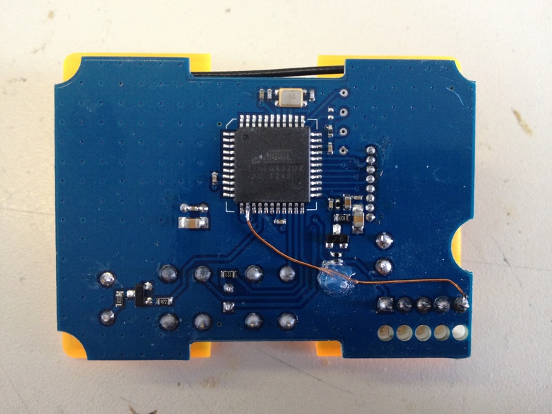
For the Blue board, what do you mean by "The blue one needs a wire added, and the programming pads need to be soldered"?
I checked, the DATA and CLK signals are connected to the same pins like on my Green PCB version.
Here is a picture of the board before soldering the programming wires:
For the Blue board, what do you mean by "The blue one needs a wire added, and the programming pads need to be soldered"?
I checked, the DATA and CLK signals are connected to the same pins like on my Green PCB version.
Here is a picture of the board before soldering the programming wires:
Last edited by LapinFou on Wed Apr 12, 2017 1:15 pm, edited 1 time in total.
Re: Orange Module running MULTI protocol
OK. Have made some progress. With the option -e (Erase flash and EEPROM) the program process has been successful. 
The green LED of the Orange module is now flashing and the module is recognized by OpenTX 2.2
Last step will be to test it with a BNF model.
I read the lock bits and got 0xFC
Maybe the 2 LSB @0x0 are the ones locking the read/write process?
Mike, do you have an explanation about this weird issue?
[EDIT] I just checked with my Orange V1.2. LB are 0xFF, not 0xFC. This was certainly my issue.
-
MikeB
- 9x Developer
- Posts: 17992
- Joined: Tue Dec 27, 2011 1:24 pm
- Country: -
- Location: Poole, Dorset, UK
Re: Orange Module running MULTI protocol
I was just going to explain that! The code I have running in ersky9x to flash the Orange module using PDI checks the lock bits and erases the chip if they are set.
If you have flashed using the file from "MultiOrangeBoot.zip" in the first post, you will have the bootloader installed (needs the fuses set to use it properly). With that, you may flash the module using a FTDI type device plugged into the module socket, so not needing soldering to the pads anymore.
ersky9x also includes an option to flash the module this way when it is plugged in.
Mike.
erskyTx/er9x developer
The difficult we do immediately,
The impossible takes a little longer!
The difficult we do immediately,
The impossible takes a little longer!
Re: Orange Module running MULTI protocol
Thanks Mike for confirming!
For now I left the LB fuse to 0xFC. Do you think this can be an issue to run the Multi firmware? Shall I changed the LB to 0xFF?
Yes, I saw your MultiOrangeBoot, but I can only program .hex file, not .bin file. By the way, I didn't see the explanation how to use/plug a FTDI with bootloader. Could you tell me more about that?
Seb
-
MikeB
- 9x Developer
- Posts: 17992
- Joined: Tue Dec 27, 2011 1:24 pm
- Country: -
- Location: Poole, Dorset, UK
Re: Orange Module running MULTI protocol
I thought I flashed the .bin file using an AVRISP-II (from Avrdudess) OK. Are you sure you can't use a .bin file?
The bootloader looks like an Arduino bootloader, serial data in to the module on the top pin and serial data out from the module on the bottom pin. Use 57600 baud.
Mike.
The bootloader looks like an Arduino bootloader, serial data in to the module on the top pin and serial data out from the module on the bottom pin. Use 57600 baud.
Mike.
erskyTx/er9x developer
The difficult we do immediately,
The impossible takes a little longer!
The difficult we do immediately,
The impossible takes a little longer!
Re: Orange Module running MULTI protocol
I will check tomorrow. I got few questions:
1. The bootloader must be programmed in the flash or the EEPROM?
2. To use the bootloader, was is the correct LB fuses code? 0xFF?
3. Since the top/bottom of the module is somehow relative, here is what I think I understood: serial pins for the communication are the 2 at the begin/end of the 5 JR pins. The serial data in (which must be connected to the FDTI's TXD) is the one next to the ground pin. The serial data out (connected to the FDTI's RXD) is the pin to the other extremity. To summarize -> 1: data in, 2: GND, 3: Vcc, 4: unused, 5: data out. Did I get right?
4. To update the firmware, I can use a classic FTDI (57600 Baud) plug on the module. Using the same numbering as point 3, then I must plug the FTDI -> 1: TXD, 2: GND, 3: 5V, 4: unused, 5: RXD. FTDI configured in 3.3V mode (not 5V, otherwise modified board with a wire and no serial resistor can be damaged). Is it correct?
Envoyé de mon Nexus 10 en utilisant Tapatalk
-
MikeB
- 9x Developer
- Posts: 17992
- Joined: Tue Dec 27, 2011 1:24 pm
- Country: -
- Location: Poole, Dorset, UK
Re: Orange Module running MULTI protocol
1. The bootloader goes into the flash. The XMEGA, has an extra 4K of flash specifically for a bootloader (36K flash in total).
2. Lock bits should be 0xFF (nothing locked). Fuse 2 should have the 0x40 bit cleared to 0.
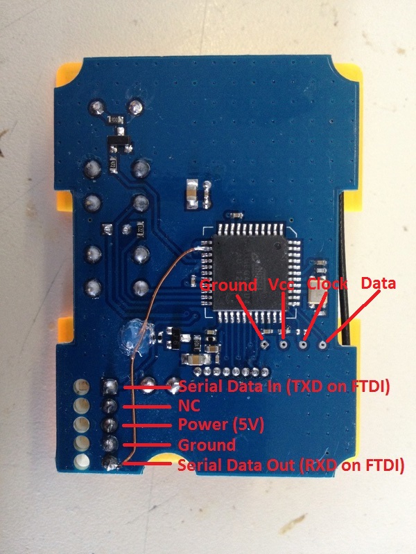
3. The "bottom" pin is the one with the extra wire connected to it. This is data OUT from the module so connects to the FTDI RXD signal. So following your numbering:
Pin 1 (bottom, closest to the end of the module) serial data OUT.
Pin 2 Ground.
Pin 3 Vcc.
Pin 4 unused.
Pin 5 serial data IN (TXD on FTDI).
4. There is a serial resistor (220 ohm) on the serial IN signal, so a 5v FTDI is OK to use.
Mike.
2. Lock bits should be 0xFF (nothing locked). Fuse 2 should have the 0x40 bit cleared to 0.
3. The "bottom" pin is the one with the extra wire connected to it. This is data OUT from the module so connects to the FTDI RXD signal. So following your numbering:
Pin 1 (bottom, closest to the end of the module) serial data OUT.
Pin 2 Ground.
Pin 3 Vcc.
Pin 4 unused.
Pin 5 serial data IN (TXD on FTDI).
4. There is a serial resistor (220 ohm) on the serial IN signal, so a 5v FTDI is OK to use.
Mike.
erskyTx/er9x developer
The difficult we do immediately,
The impossible takes a little longer!
The difficult we do immediately,
The impossible takes a little longer!
Re: Orange Module running MULTI protocol
Hi Mike, thanks for your answers.
1. I checked AVRDUDESS, only .hex and .eep extensions are supported.
2. To summarize, here is a picture:
3. If a 5V FDTI is used, are you sure it will work ? Because the serial data Out will be 3.3V. According the FTDI spec the high state is typically 4.1V...
1. I checked AVRDUDESS, only .hex and .eep extensions are supported.
2. To summarize, here is a picture:
3. If a 5V FDTI is used, are you sure it will work ? Because the serial data Out will be 3.3V. According the FTDI spec the high state is typically 4.1V...
-
MikeB
- 9x Developer
- Posts: 17992
- Joined: Tue Dec 27, 2011 1:24 pm
- Country: -
- Location: Poole, Dorset, UK
Re: Orange Module running MULTI protocol
Avrdudess 2.4 has the option of showing ALL files, as well as .hex and .eep. I believe I used that to select a .bin file.
The picture is correct.
I used a FTDI type device on a Multi 4-in-1 board that also runs from 3.3V.
Mike.
The picture is correct.
I used a FTDI type device on a Multi 4-in-1 board that also runs from 3.3V.
Mike.
erskyTx/er9x developer
The difficult we do immediately,
The impossible takes a little longer!
The difficult we do immediately,
The impossible takes a little longer!
Re: Orange Module running MULTI protocol
Thanks Mike,
I will try the FTDI solution later. Keep you in touch.
Thanks for all your work.
I will try the FTDI solution later. Keep you in touch.
Thanks for all your work.
Re: Orange Module running MULTI protocol
FTDI works ok using a 5 volt device and avrdude for me. I used a Taranis x9d plus with Mike's recommended PDI programming connections and ERsky with the PDI addon's. At first I was trying to power from the module bay, but the taranis does not power up the module unless it's ready and selected in a model seems like so I was getting no voltage output. I switched to using an external 6 volt battery and only using gnd, clk and data from the taranis and this worked fine to do the initial flash of Mike's bootloader image. I then used the ersky bootloader to load my own customized version of the multi protocol code using the load multi option (I like TAER as my channel order) and this worked perfectly. I used the "build_orange.cmd" to build the orange multi code from the diy multiprotocol code and that worked fine so I assume that's all good.
Just for giggles, I thought I'd try the ftdi method using serial and avrdude and this worked fine as well. Module works perfectly. Thanks MIke for a great modification!
Edit: ONe oddity and it is because I loaded my own version of the diy code which does not include MIke's mod to auto run the bootloader. I had to hold the bind button on module power up to force boot the bootloader to run (steady led vs flashing led). By the way this was all done to a green board new v1.2 hobbyking orangetx module which also required the addition of jumpers for r1 and r13 since the resistors are not there for this version.
Last edited by Dilbert66 on Thu Apr 13, 2017 1:39 pm, edited 2 times in total.
Re: Orange Module running MULTI protocol
Thanks for your feedback. I will try ASAP. I will post my result.
Re: Orange Module running MULTI protocol
MIke, do you also recommended setting the EESAVE bit 3 in fuse 4 to prevent eeprom erase during flash to preserve the Transmitter Bind ID similar to what is recommended for the diy multi proocol code or is that already handled by the bootloader? I'd rather not have to rebind every time I reflash.MikeB wrote: ↑Wed Apr 12, 2017 11:57 pm 1. The bootloader goes into the flash. The XMEGA, has an extra 4K of flash specifically for a bootloader (36K flash in total).
2. Lock bits should be 0xFF (nothing locked). Fuse 2 should have the 0x40 bit cleared to 0.
3. The "bottom" pin is the one with the extra wire connected to it. This is data OUT from the module so connects to the FTDI RXD signal. So following your numbering:
Pin 1 (bottom, closest to the end of the module) serial data OUT.
Pin 2 Ground.
Pin 3 Vcc.
Pin 4 unused.
Pin 5 serial data IN (TXD on FTDI).
4. There is a serial resistor (220 ohm) on the serial IN signal, so a 5v FTDI is OK to use.
Mike.
-
MikeB
- 9x Developer
- Posts: 17992
- Joined: Tue Dec 27, 2011 1:24 pm
- Country: -
- Location: Poole, Dorset, UK
Re: Orange Module running MULTI protocol
Unless you need to do a "chip erase", then the EEPROM is kept. Using the bootloader then no "chip erase" is performed. I believe using the PDI, no "chip erase" is performed unless the lockbits are set then a "chip erase" is needed to clear them.
I'd need to check the code, but it is possible the Multi code uses a unique ID from the Rf chip.
Mike.
I'd need to check the code, but it is possible the Multi code uses a unique ID from the Rf chip.
Mike.
erskyTx/er9x developer
The difficult we do immediately,
The impossible takes a little longer!
The difficult we do immediately,
The impossible takes a little longer!
Re: Orange Module running MULTI protocol
I confirmed. Bind process is using the unique ID present in the CYRF6936 chipset.
Re: Orange Module running MULTI protocol
Tks folks. That's good to know. Interesting that the original OrangeTX code uses the second switch to allow changing the unique ID. I don't know if the odds of conflicting with some else warrants having the same functionality with the DIY code or if the ID is random enough to make those odds very slim...
Alain
Alain
Re: Orange Module running MULTI protocol
quick question, i have a green board version orangerx module v1.2 without the dip switches on the back and with the antenna external in the top left corner using a a small ufl to sma pigtail and my question is about the resistors mine is lacking on R1 and R13 you mentioned, if they are missing do I have to solder a wire between the to of them? or do I have to solder a wire to ground for each of them? thanks Mike in advance, The help you have given out so far in this thread is incredible! We all owe you for all of your hard work!!!
Re: Orange Module running MULTI protocol
oh and i forgot to ask i have a 9xr Pro with er9x v220 Bootloader v2.1 and i saw somewhere you say something about revision r221 but i dont see that anywhere on the er9x homepage? so when i try and flash it just says flash failed right away with no numbers below it like you guys were talking about earlier in the post that there should be numbers if it fails to flash, any ideas? I need your opensource voodoo wisdom to help me get this done. I want telemetry to work on this module!!! and do be able to use select dsm2, dsmx, or other protocols and also not have any of the lag it takes to go to ppm and use a straight serial connection!
Re: Orange Module running MULTI protocol
Mike? anyone? help lol
-
MikeB
- 9x Developer
- Posts: 17992
- Joined: Tue Dec 27, 2011 1:24 pm
- Country: -
- Location: Poole, Dorset, UK
Re: Orange Module running MULTI protocol
Yes to soldering a wire to replace the missing resistors, across each one, not to ground.
r221 is not released, but test versions are here: viewtopic.php?f=7&t=4676.
Mike.
r221 is not released, but test versions are here: viewtopic.php?f=7&t=4676.
Mike.
erskyTx/er9x developer
The difficult we do immediately,
The impossible takes a little longer!
The difficult we do immediately,
The impossible takes a little longer!
Re: Orange Module running MULTI protocol
thanks mike, got it all figured out last night, found the c4 test version of 221 before your post lol and then bridged the r1 and r13 and flashed it with the bootloader xmega and boom good to go! thanks so much, they only problem i had was setting the TAER up because even in the Radio Setup->Controls->Channel Order, if i changed it to AETR or TAER it would make no difference, I had to go in manually and change them in the mix menu, But now I just saw in a few posts above that someone changed and you tested and posted a working TAER version and now that ive flashed the module it has the new bootloader so I can use the serial connection it now has to flash the new TAER firmware right from the module bay, that all sound about right Mike? if so i will be doing that ASAP and throwing that TAER version on my SD card and flashing away and then thats one less thing to ever worry about again!!!! Thanks Again!!!!
Re: Orange Module running MULTI protocol
oh i also wanted to ask about the file "MultiprotocolTAER.ino.xmega32d4.zip" still has the other protocols in it correct? because I remember reading the other guy who was working on doing this that you helped was only interested in the DSM protocols and I wanted to make sure that the others didnt get removed from this TAER version of the multiorangerx firmware. Thanks
-
MikeB
- 9x Developer
- Posts: 17992
- Joined: Tue Dec 27, 2011 1:24 pm
- Country: -
- Location: Poole, Dorset, UK
Re: Orange Module running MULTI protocol
I think that all sounds OK. I'm not sure what is in the .zip you mention.
The source code on Github may be compiled in the Arduino IDE for the Orange module, with the protocols you want being set in the _config.h file.
Mike.
The source code on Github may be compiled in the Arduino IDE for the Orange module, with the protocols you want being set in the _config.h file.
Mike.
erskyTx/er9x developer
The difficult we do immediately,
The impossible takes a little longer!
The difficult we do immediately,
The impossible takes a little longer!