Page 1 of 23
Orange Module running MULTI protocol
Posted: Sun Apr 24, 2016 11:01 pm
by MikeB
There is a thread on RCGroups describing how to build your own Tx module. This supports various RF sub-modules and uses an Arduino Pro Mini to control them. One of the RF options is DSM2/DSMX. It uses a protocol called MULTI to communicate with the transmitter. The firmware is open source.
Details for all this are here:
http://www.rcgroups.com/forums/showthread.php?t=2165676.
I have ported the firmware so it runs on the Orange DSM Tx module(s). One advantage of using this is it works with the BNF models the original firmware fails with.
The main problem is flashing the new firmware. The Orange modules use an Atmel XMEGA device that needs to be flashed using a "PDI" programming interface, so a USBASP cannot be used.
To help with this, I've coded a PDI XMEGA programmer in the "maintenance mode" of ersky9x for the 9XR-PRO and the 9Xtreme. This is available in the file ersky9xProvR219m.zip (or later) at:
viewtopic.php?f=7&t=4676&p=65894#p65894.
Since I created a bootloader for the Orange module, it now means you may only need to flash the bootloader to the module, then you can flash the application from a radio running ersky9x, or possibly using a FTDI device (not tested), but you will need a resistor in the Tx signal from the FTDI device if it outputs 5V.
You still need to get the bootloader onto the module. As a way of doing this, I've produced a sketch for an Arduino Pro Mini that contains the bootloader code, and also PDI programming code.
To use, connect:
Ground from the module to ground on the Arduino.
Vcc (3.3V) from the module to Raw (or maybe VCC) on the Arduino (I tested using Raw).
PDI Clock from the module to IO2 on the Arduino.
PDI Data from the module to IO3 on the Arduino.
Power the module, the Arduino will be powered from the 3.3V from the module.
After a couple of seconds, the LED on the Arduino will flash, around once per second if the bootloader flashed OK, and 5 times per second if it failed.
In theory, the Arduino is running too fast (16KHz) for operation from 3.3V, but it should work, and only needs to flash the module once.
The sketch for the Arduino:
- pdiMini.zip
- 12-Aug-2017 12:00
Sketch for Arduino Mini - (6.26 KiB) Downloaded 829 times
I've created some instructions on how to do all this in the attached .pdf file ("PDIflashing.pdf").
- PDIflashing3.pdf
- 05-Nov-2017 21:21
Add instructions for using a Pro Mini to flash the bootloader. - (175.02 KiB) Downloaded 1037 times
- PDIflashing2.pdf
- 26-Apr-2016 15:58
Update includes SKY/AR9X instructions - (166.13 KiB) Downloaded 1637 times
The firmware file(s) for the Orange module is also attached. Note that some older modules are blue, and these need the 'blue' version of the file.
I've built files for both the Green and Blue boards from sources that support the bootloader. These files are the 1.1.6.21 sources, with the addition of improvments for the FrSky X telemetry protocol, and they also check for an attempt to flash the bootloader and drop out to the bootloader.
Use these files if you have er9x/ersky9x/openTx with the DSM changes (Sep 2016) that provide DSM2-22, DSM2-11, DSMX-22, DSMX-11 and AUTO, sub-protocol options.
- MultiOrangeBoot.zip
- 21-Mar-2017 23:39
Multi 1.1.6.20 for Orange module with bootloader
Needs to be flashed using ersky9x test version r221 C2 or later - (10.59 KiB) Downloaded 835 times
Instructions on modifying a Taranis to be able to flash a XMEGA device:
Note: On a standard Taranis (not a PLUS), you will need to remove RP1 from the main board for this to work, see: viewtopic.php?f=40&t=8753&p=118349#p118349.
- TaranisPb.pdf
- 13-Jun-2016 18:36
- (209.07 KiB) Downloaded 1346 times
The "Blue" module also needs a track cut to allow it to work. The picture in the PDF file shows a wire that needs to be added to allow telemetry to be used. The processor pin the wire connects to is tracked to the next pin (corner pin). This connection needs to be cut, while still leaving the corner pin connecting to the track (it is the serial input to the processor), see this diagram:
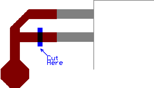
- Orange.png (2.1 KiB) Viewed 50278 times
Here are some pictures of how I wired to a 'Blue' module:
I have some jumper wires that are in pairs I used, sometimes only one of the pair is connected.
At the bottom of the first picture the red wire is soldered to the Data pad and the yellow wire is soldered to the Clk pad. When these wires reach the pin header at the left of the picture, the yellow wire continues yellow (the green wire of the jumper cable is not connected), and the red wire continues as white (the blue wire is not connected).
At the top of the first picture there is a red and a black pair connected to the Gnd and Power of the 5-way socket.
At the 9XR-PRO end, the wires are plugged on the the module bay pins, the yellow (Clk) wire at the bottom, then the black (Gnd) and the red (power), then miss a pin and the white (Data) to the top pin.
You will need to check the module to make sure the serial data gets to the correct pin of the processor. All the modules I tested were originally intended for the 9XR-PRO to use the antenna in the handle. As such, they used a serial connection.
If the board is Green, and looks like the image below, check for the two resistors R1 and R13, they are missing on the attached image. When fitted, they are 10 ohms, but a direct short will work as well. R1 is needed to respond to the MULTI commands, R13 is needed for telemetry.
If you have a "blue" board, check for a connection between the PPM pin of the module connector (top pin), and the processor corner pin just beside where the wire mod is shown. On my board, this connection measures 220 ohms.
Mike.
Orange Module running MULTI protocol
Posted: Mon Apr 25, 2016 4:07 am
by Daedalus66
As I've reported elsewhere, I've tested an Orange module (green board) upgraded with Mike's ported Multi firmware, both on the bench and in the air. In particular, I tested it with three of the UMX DSMX models that it previously would not control. It worked perfectly. I've also flown it with a Lemon DSMX compatible receiver. Range looks good in all cases. More testing to come.
Update:
Ground range testing indicates full power range at least equal to "full range" Spektrum transmitters. This means well in excess of normal visual flying distance.
Range in Low Power mode is about 1/12 that in High Power mode. Low power is for indoor, micro models and other close-in flying.
Range Check mode uses lower power setting than Spektrum, so expect a given receiver to show about 2/3 range. I will be using 20 paces (about 15m) instead of the traditional 30 paces as my go/no go standard for testing at the beginning of a session. In practice, many receivers will give much more range than this (e.g., 90m+ for a Lemon Stabilizer).
My tests were with the module in a 9XR Pro using the internal antenna. I have been using the internal antenna with an older Orange RX module for two years with excellent results.
Re: Orange Module running MULTI protocol
Posted: Mon Apr 25, 2016 6:01 am
by marcusramberg
Is it possible to get this flashing firmware on ar9x as well?
Sent from my iPad using Tapatalk
Re: Orange Module running MULTI protocol
Posted: Mon Apr 25, 2016 9:08 am
by MikeB
It may be, but I have still to check for voltage levels and available outputs. The 9XR-PRO and the 9Xtreme both have a full SPort connection on pin 5, that allows the signal to be used as an output. At the least, on the AR9X board, the back board will need modifying so pin 2 is available and the COM1 output will need to be connected to it to provide a second output signal.
Mike.
Re: Orange Module running MULTI protocol
Posted: Tue Apr 26, 2016 12:13 pm
by MikeB
OK, the AR9X is now able to flash the Orange module. I'll need to update the instructions and post a new test version of ersky9x. It should be possible to use a SKY board, but that will need a transistor buffer, with a base resistor, for the Clk signal, and I haven't tested a SKY board yet.
The AR9X board does need the COM1 output from the header (pin next to the SPort pin) wired to pin 2 (one down from the top) in the module bay, and the back board needs the ground connections (on both sides) removed from this pin. The signal is a 3.3V signal driven low by a transistor and high by a pullup resistor.
Mike.
Re: Orange Module running MULTI protocol
Posted: Tue Apr 26, 2016 3:02 pm
by MikeB
I've added some updated instructions on the first post.These include the SKY and AR9X boards.
I've also posted a firmware update, for these boards, on the ersky9x test version thread.
Mike.
Re: Orange Module running MULTI protocol
Posted: Tue Apr 26, 2016 4:42 pm
by marcusramberg
MikeB wrote:OK, the AR9X is now able to flash the Orange module. I'll need to update the instructions and post a new test version of ersky9x. It should be possible to use a SKY board, but that will need a transistor buffer, with a base resistor, for the Clk signal, and I haven't tested a SKY board yet.
Awesome work, Mike. Thank you!
Re: Orange Module running MULTI protocol
Posted: Thu Apr 28, 2016 11:01 am
by MikeB
All the modules that have been flashed during testing were prototype modules. These did not have any lock bits set to protect the flash memory. It is possible that production modules have lock bits set, preventing the flashing fro taking place. If this is the case, then you will likely see correct signature values (1E95 4101 or 1E95 4201) at the bottom of the screen, and the flashing appear to only take a second or so, but the module then still operate as before.
If lock bits are set, I'll need to add a "chip erase" operation to clear them at the start of flashing. I'm looking into this now.
Mike.
Re: Orange Module running MULTI protocol
Posted: Thu Apr 28, 2016 11:14 am
by jhsa
It looks like they didn't want someone to do a better job, and actually make it work


Thanks Mike
João
Re: Orange Module running MULTI protocol
Posted: Thu Apr 28, 2016 6:26 pm
by MikeB
I've updated the firmware for the 'PRO (file ersky9xr_romXMerase.zip on th test version post).
This now reads the lockbits, and if it finds the flash is locked, it issues an "erase chip" command before flashing the new firmware.
Mike.
Re: Orange Module running MULTI protocol
Posted: Fri Apr 29, 2016 9:20 am
by LapinFou
Hi Mike,
I'm very impressed by your work and skills!!
I own a Taranis. Is it possible to have a maintenance mode for the Taranis?
Re: Orange Module running MULTI protocol
Posted: Fri Apr 29, 2016 10:56 am
by MikeB
So far I haven't found a way to get the Taranis to do the PDI flashing. The PDI needs a bi-directional signal, at 3.3V levels, that has a high input impedance (>50K), and the Taranis doesn't have one.
Mike.
Re: Orange Module running MULTI protocol
Posted: Fri Apr 29, 2016 10:59 am
by MikeB
I've updated the first post to include details for checking the serial data is connected on the board.
Mike.
Orange Module running MULTI protocol
Posted: Fri Apr 29, 2016 12:51 pm
by Daedalus66
A brief history of the Orange DSM2/DSMX module, just to situate things.
The original module came out, as I recall, in November 2012. Those of us who ordered immediately found it didn't control channel 2 correctly due to a firmware error. HobbyKing recognized this within days and sent free replacements to all who received one of the first ones. By December 2012 the properly working module was on sale in both JR and Futaba type cases. The label on this module indicated "DSM2" but in fact from the very beginning it was DSM2/DSMX compatible. It can be switched to the next of the four receiver types by pressing the Bind button three times in quick succession. This module works correctly with all types of DSM2 and DSMX receivers, including Spektrum stand alone receivers and the various BNF UMX models by Blade, E-Flite, Parkzone, etc. it also worked with receivers by Orange and Lemon. This is the module with blue board described by Mike.
Orange then "improved" the design in 2014 by mounting the antenna directly on a secondary circuit board, thereby thwarting DIY fixes to the antenna setup that took advantage of the pigtail connection in the previous version. In other respects, the 2014 version functions just like the 2012 module and I'm assuming it can be reflashed in the same way. However, like its predecessor it is fully functional with all types of receiver, so there's less incentive to do so than with current modules.
Finally in early 2015, two new Orange DSMX/DSM2 modules with green boards were issued to replace the previous one. The Basic module appeared very similar, except that the antenna was mounted in the top left corner of the module, instead of near the bottom. This is a slight improvement. The other module is called the Switchable and is shown in Mike's first picture. The switches control mode, power and channel order and also allow Walkera protocol to be selected. With the switches OFF, it works just like the Basic.
The big frustration with both 2015 OrangeRX modules is that they simply do not support the BNF series of UMX and SAFE models such as Radian UMX, NanoQX, Sport Cub S, 180QX, and so on. What generally happens is that channel 1 (Throttle) is dead or very erratic. These popular BNF models are the very reason that many people want a DSM module for their 9XR Pro, 9XR, Taranis, etc. OrangeRX still do not appear to have addressed (or even acknowledged) this problem.
Mike's upgrade of the firmware of the Orange modules to use the relevant portions of the Multi protocol offers a way to overcome this limitation.
Re: Orange Module running MULTI protocol
Posted: Fri Apr 29, 2016 2:34 pm
by ShowMaster
What about this multi protocol module? Will it work with our 9x conversions or pro?
2.4G CC2500 A7105 Flysky Frsky Devo DSM2 Multiprotocol TX Module With Antenna
https://bnc.lt/4Sug/w2JRf9nfYs
Re: Orange Module running MULTI protocol
Posted: Fri Apr 29, 2016 2:42 pm
by jhsa
Here is the best place to ask that question..
http://www.rcgroups.com/forums/showthread.php?t=2165676
The reason is, some of those multi modules that are being sold might not be 100% compatible with the original DIY project..
But if there are no compability problems it should work, yes. I have built a couple of those modules. One of them I use for controlling some microquad toy I have.. I works really well..
I have another that was sent to me for testing that can control Frsky, Flysky, and other protocol for my little quad which I don't remember the name right now.. The quad is the CX10.
I could eventually also control DSMX/2, but i didn't install the RF part for it..
For DSMX I flashed my pre-release orange module (Which I believe you also have??) with Mike's firmware, and it seems to be working.. Will have to test the telemetry next.
João
Re: Orange Module running MULTI protocol
Posted: Fri Apr 29, 2016 3:01 pm
by MikeB
I've just realised that the 'Blue' module had a track cut done to it when adding the wire for the telemetry. This track cut needs to be done even if you don't add the wire. Details are in the first post. I had forgotton I'd done this, and the cut is hidden by the wire.
Take care to only disconnect the pin to which the wire goes and leave the corner pin still connected to the track (it is the serial input pin).
Mike.
Re: Orange Module running MULTI protocol
Posted: Sat Apr 30, 2016 6:08 pm
by chubb
Does this work with the orange RX module that was release exclusively for the 9xr-pro?
Sent from my LG-H811 using Tapatalk
Re: Orange Module running MULTI protocol
Posted: Sat Apr 30, 2016 6:40 pm
by MikeB
Yes, and since that module used serial input and telemetry output it is already wired for use. In fact, the green modules I used for the development are that type.
Mike.
Re: Orange Module running MULTI protocol
Posted: Mon May 02, 2016 12:29 pm
by LapinFou
MikeB wrote:So far I haven't found a way to get the Taranis to do the PDI flashing. The PDI needs a bi-directional signal, at 3.3V levels, that has a high input impedance (>50K), and the Taranis doesn't have one.
Mike.
Thanks for the information.
Just another question, is it not possible to flash the device with the existing Orange USB dongle?
OrangeRX USB Firmware Update Kit
Re: Orange Module running MULTI protocol
Posted: Mon May 02, 2016 12:55 pm
by Daedalus66
No, unfortunately.
Re: Orange Module running MULTI protocol
Posted: Mon May 02, 2016 4:10 pm
by MikeB
My understanding is the bootloader this uses requires the firmware file to be encoded in some way. I don't know what the encoding is.
Mike.
Re: Orange Module running MULTI protocol
Posted: Mon May 02, 2016 5:10 pm
by LapinFou
It is a shame

Thank for the answer.
Re: Orange Module running MULTI protocol
Posted: Mon May 02, 2016 6:05 pm
by MikeB
I agree. Unfortunately, I don't have the bootloader code to be able to even start on trying to use it.
I hope to write a bootloader that we can use in this way, but you will still need a method of flashing the bootloader to start with.
I do have another alternative I'm considering. This is program an Arduino Pro Mini to work either as a PDI programmer, or, more likely, just have the required target firmware embedded in a program that does the flashing.
Mike.
Orange Module running MULTI protocol
Posted: Mon May 02, 2016 8:52 pm
by Daedalus66
chubb wrote:Does this work with the orange RX module that was release exclusively for the 9xr-pro?
Sent from my LG-H811 using Tapatalk
It does indeed.
I just finished flashing one of the orange DSM internal telemetry modules to Mike's port of the Multi code. The result works as it should.
I haven't yet done a thorough test as I have a problem getting good contact with the pins in the 9XR Pro, which are a bit short. I may have to install longer ones to ensure a reliable connection.
Re: Orange Module running MULTI protocol
Posted: Fri May 13, 2016 10:01 pm
by Spainman
I would love to try this fw and get rid of ppm, so I've been trying to find information and it's my understanding that OpenTx doesn't 'officially' support the MULTI protocol. Is that right and the only option (actually a non-option from my perspective) are the customized OpenTx versions posted in the rcgroups thread? Searching for issues with 'multi' on github did not bring up anything. No official support, not even planned?
Re: Orange Module running MULTI protocol
Posted: Fri May 13, 2016 10:09 pm
by Kilrah
Support is in for 2.2 AFAIK.
Re: Orange Module running MULTI protocol
Posted: Fri May 13, 2016 10:18 pm
by MikeB
Spainman wrote:the only option are the customized OpenTx versions posted in the rcgroups thread?
Ersky9x for the Taranis now fully supports the MULTI protocol, complete with telemetry support that includes the DSM telemetry handled by this module.
Mike.
Re: Orange Module running MULTI protocol
Posted: Fri May 13, 2016 11:07 pm
by Spainman
@Mike: Sorry, I wasn't specific enough. I was referring to OpenTx only.
@Kilrah: Seems I was blind - searched again and found that it's already merged in next.
Thank you both for the clarification.
Re: Orange Module running MULTI protocol
Posted: Fri May 13, 2016 11:34 pm
by jhsa
If you have a Taranis, I don't think you can even flash the Orange module with Multi using it. as far as I know the only platforms capable of flashing the module are the 9XR-PRO and the Ar9x Board with Ersky9x. Not sure about the skyboard.
The processor in the orange nodule cannot be flashed using a normal UsbAsp programmer, so Mike coded a programmer on those radios..
João